1950 Emerson TV resurrection attempt
Posts: 2,198
Threads: 159
Joined: Jan 2013
City: Westland, MI
Nice project, Tim! That chassis looks like an exercise in patience ... mighty tight wiring package there. Take care and BE HEALTHY! Gary
"Don't pity the dead, pity the living, above all, those living without love."
Professor Albus Dumbledore
Gary - Westland Michigan
Posts: 1,222
Threads: 86
Joined: Jan 2014
City: Annapolis, IL
State, Province, Country: USA
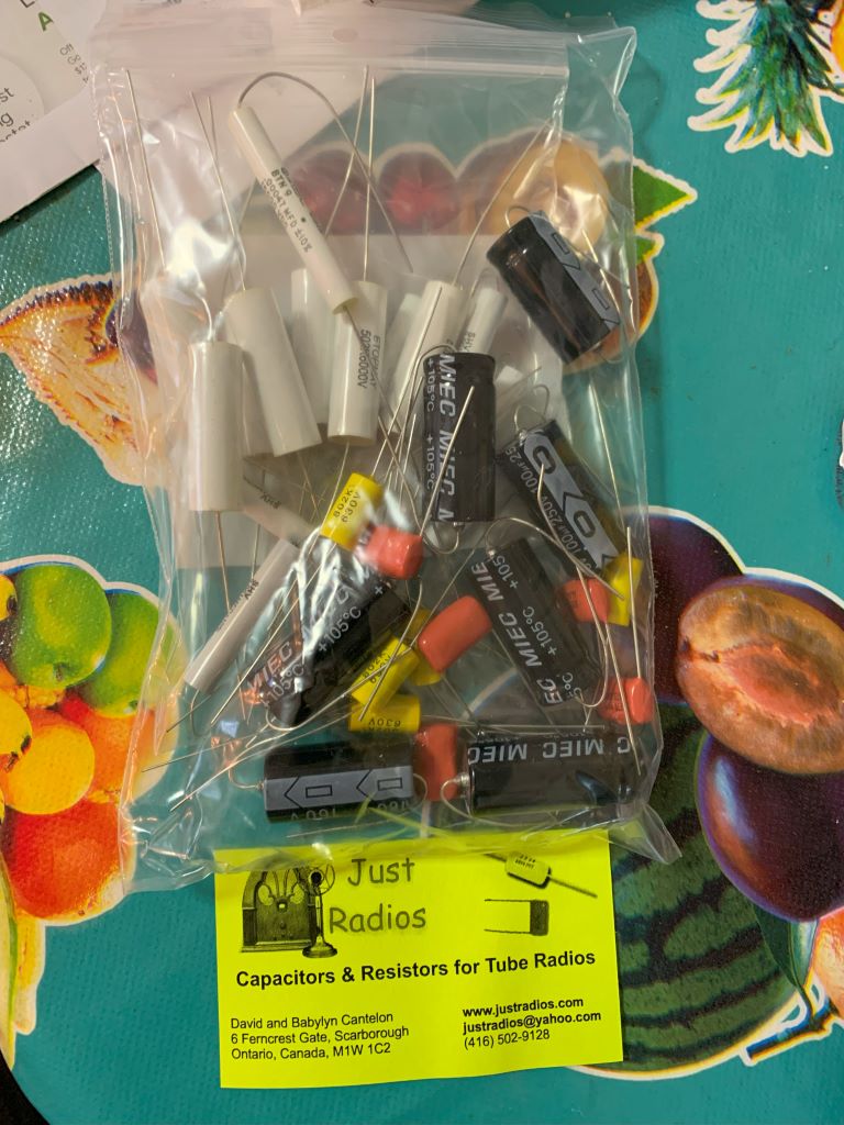
Been awhile since I've even been in the radio room. Work work work, kids graduating, going into college, and the list goes on and on, but, look what showed up for my Emmy!
I still need to order some resisterators for the focus (Mr Anderson mentioned the correct ones from Mouser), but this should allow me to get those monster capacas replaced and see if I can get a raster & picture. Got enough big caps to do my Sentinal too and some extras for no good reason.
If I could find the place called "Somewhere", I could find "Anything" 
Tim
Jesus cried out and said, "Whoever believes in me , believes not in me but in him who sent me" John 12:44
Posts: 1,222
Threads: 86
Joined: Jan 2014
City: Annapolis, IL
State, Province, Country: USA
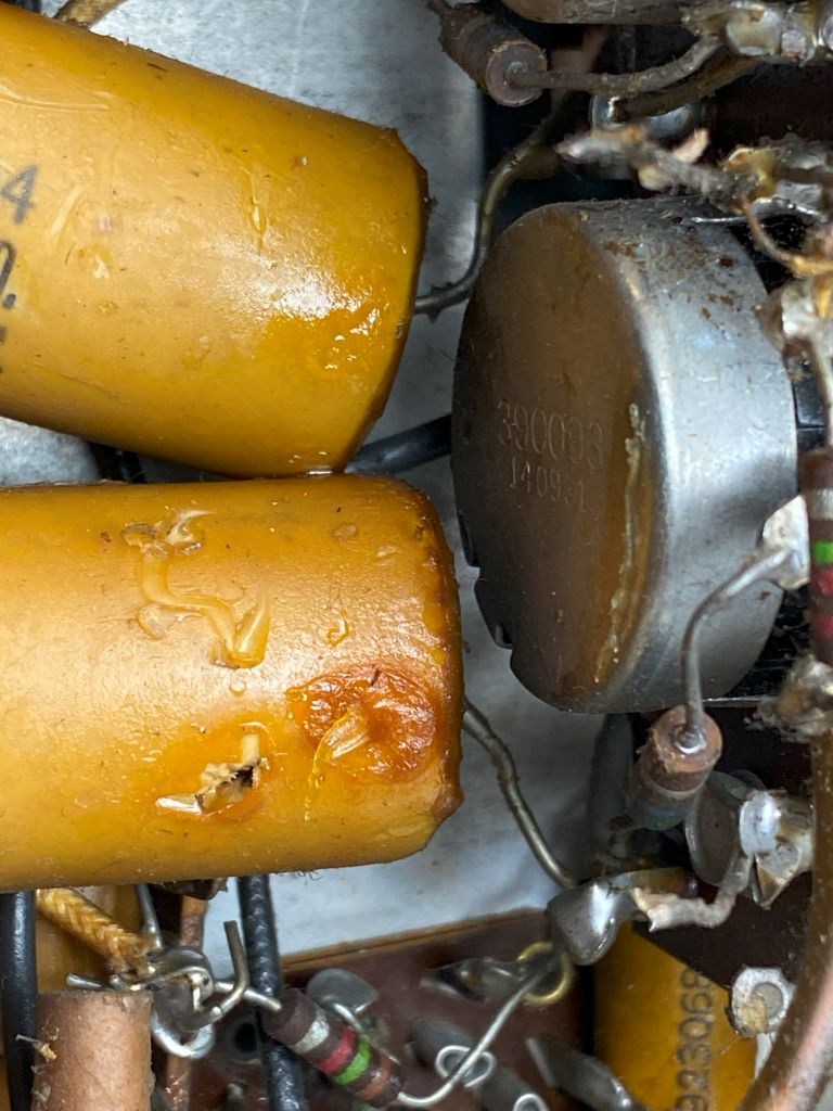
With the rain and all, I've been back in the radio room hoping to finish a few that have been sitting on the bench since the 1st of the year - or longer. Wow! It takes some time to remember where a person was, even with notes. I do have some videos that I made which help a lot. I want to get this finished so I can clean and start a Predicta and possible amp build, so here's where I am. 1st, I want to thank Mr Anderson for his very helpful video on this set. Funny how I can "find" something, then he does a video right before I start work on it, which is very helpful. I re-watched the Emerson video to get parts I might need written down, and some potential problems to check for. One of the problems he mentioned was that one of the 10meg resistors on the vertical divider/output had been replaced and mentioned replacing those anyway since there was quite a bit of voltage on those. I checked them and found one open! (probably the same one he saw that had been replaced) So, I don't have any laying around, which means I need to order those as well as the HV divider resistors. I started the recap on those coupler caps and HV filter caps. I decided with them out of the way I'd go ahead and replace the paper caps in the vertical, sync and video section. Boy, were those beauties buried! Vertical caps ALWAYS give trouble! Even tho I don't have ANY horizontal sweep at all! I might know why tho. Big crack in the bumbl bee caps for the horizontal. Take a look at the pics.
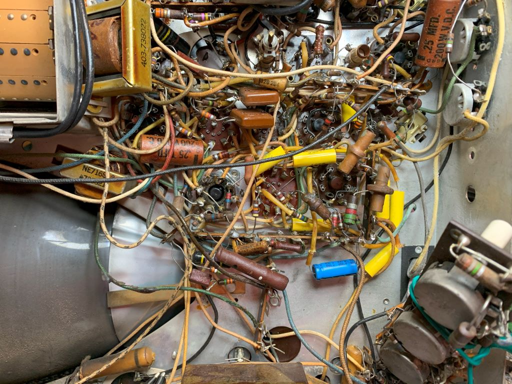
That vertical cap has a hole blown or burned in it. I did have some vertical sweep but that was buried under the HV filter cap and none of those had ever been out. Bet that and the open 10 meg resistor is what retired this set. I haven't seen anything that looks replaced, looks all original. Wish I could keep it that way but it doesn't work that way. I could re-stuff but why? Who's gonna look under the chassis unless it needs repairs. I'm taking the effort to keep parts in their original locations to avoid problems and also to locate if necessary via a Sams or something. Someone else might not be able to follow my work unless things are in their original location, and helps locate mistakes if I make any. Next I'll get the HV caps tacked in and test the set before replacing anything else.
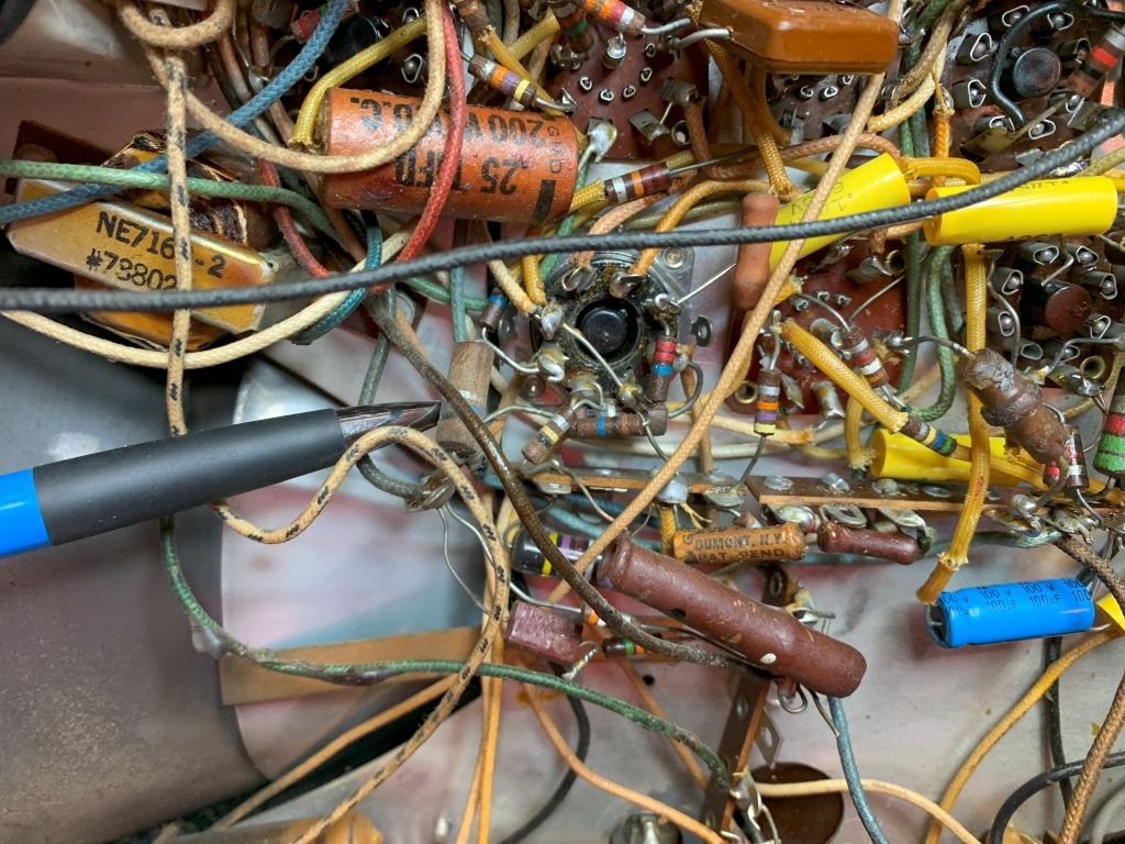
There are 2 10 meg resistors and a 22 meg on the vertical output tube. The other one is below that small resistor and is open.
If I could find the place called "Somewhere", I could find "Anything" 
Tim
Jesus cried out and said, "Whoever believes in me , believes not in me but in him who sent me" John 12:44
Posts: 1,192
Threads: 46
Joined: Feb 2015
City: Roseville, MN
The hole in that cap is to let steam out when things get cooking. :-)
Posts: 1,222
Threads: 86
Joined: Jan 2014
City: Annapolis, IL
State, Province, Country: USA
Update: While waiting on some NOS tube sockets for my amp experiment, I turned left and got back on the TV that was already occupying my bench, with parts laying nearby, still in the bags. In my previous power ups, I had a very limited vertical sweep, no horizontal at all. Poor focus and seemed the brightness would fade as I increased line voltage. After watching Mr. Anderson's video more than once, I replace the 1.8 meg resistors in the HV divider string. Then replaced the 2 10 meg resistors in the vertical output stage that connect to the coupling caps, which go to the deflection plates on the big tube. If you're following this thread, you will remember that one of those 2 10 meg resistors was open. It gave me slight deflection on the upper half of the screen. I also replaced the coupling capacitors on the H & V outputs, and the big HV cap that runs crossways. While I had things apart, I replaced the paper caps under the HV cage. I found that removing that big filter choke allowed easier access. Mose of those were soldered straight in and could simply heat, suck the solder, and pull out while heating. Some were bent and required some surgery. The picture below shows shows the replacement of the HV string resistors and the coupler caps. I do need to go back and replace a couple 22 meg resistors and insulate the hot side of the HV filter cap. I thought it was the low side until I got a little tingle and looked at the schematic!
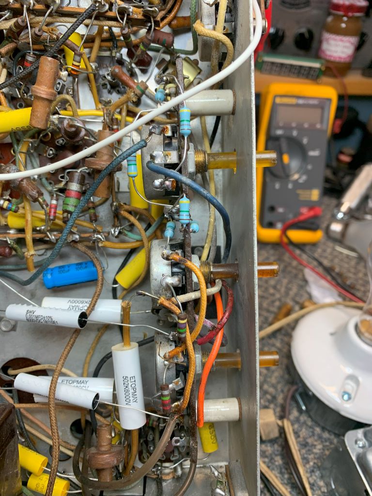
Alright, now some pictures of the power up and what happened next!
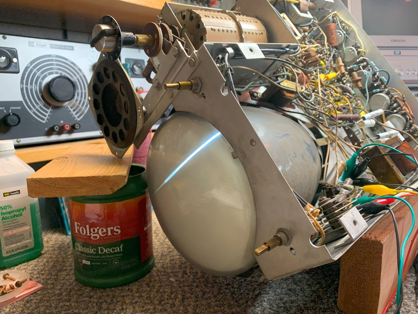
As you can see, I have full vertical deflection, but absolutely NO horizontal! I did find the focus and brightness controls worked through their range, you can see the sharp line. Huh. Why? So after some voltage checks and signal checks around the oscillator and output tube, I found I had NO plate or screen voltage on the output tube! After some tracing, I found B+ to the output trans, but nothing on the plate, screen or hot side of the coupling caps. Take a look at this circuit and you will soon see that this was NOT good news! Also note, this set does not use a common flyback as the more modern sets do. This is an electrostatic set. A whole different animal on the HV & deflection end.

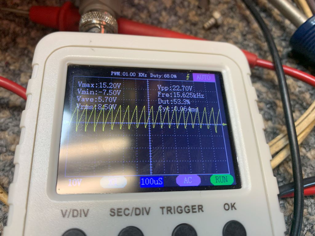
I did have a drive to the H out tube. Maybe not the best, (looks like it has some hum) but it was present, so a lack of signal didn't burn the transformer.
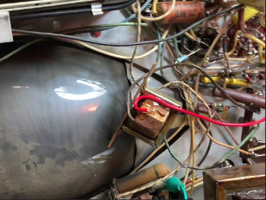
As you can see, the B+ goes through that transformer to the rest of the circuit. After the following checks, I found the there WAS continuity throughout the rest of the transformer! I checked from both ends, both ends to the plate lead, and had continuity. So, the only possible would be an open circuit from the B+ lead to the transformer. With this not exactly being something I could jump on AES or eBay and find, and knowing only about 1 person on this planet that would have one, I decided to try one last ditch effort at reviving it. I pulled it and wiggled the wires like a madman, with no results. Next, came out the surgical tools. Thankfully, this winding was accessible with only having to cut through a few layers. It wasn't broken. I CAREFULLY scraped the wires near the connection and applied the meter probe. You can imagine my delight when I saw my meter register a solid 39R! This thing has life! It looked like either bad solder or maybe corroded. I replaced the wire and all. The next pictures show the repair.

If I could find the place called "Somewhere", I could find "Anything" 
Tim
Jesus cried out and said, "Whoever believes in me , believes not in me but in him who sent me" John 12:44
Posts: 1,941
Threads: 129
Joined: May 2008
City: Omak
State, Province, Country: WA
Hello tim,
Nice job on the repair of the transformer and you sound me sometimes on the projects at hand and bob has a great utube channel !
I have a bunch of Antique tvs waiting to be restored Some day .
Sincerely Richard
Posts: 1,222
Threads: 86
Joined: Jan 2014
City: Annapolis, IL
State, Province, Country: USA
After the transformer repair, here's what happened next.
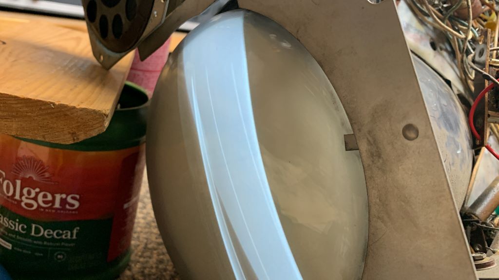
Full horizontal! Yay! Here's what things looked like after some adjustments.
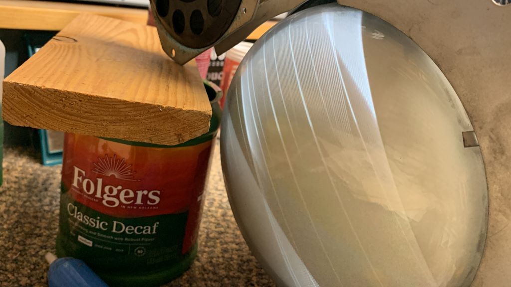
Then again in about 5 minutes. Getting dim and bloomed like in the 1st power ups. Gets worse when I raise the line voltage. A check of the HV revealed a solid 5kv when 1st powered up, then gradually dropping down to about 3500v. I'll check into that later. Probably that HV filter cap in the cage that I haven't gotten to yet. Have to pull the big tube to get the screws out. May clip it and see if that is the culprit.
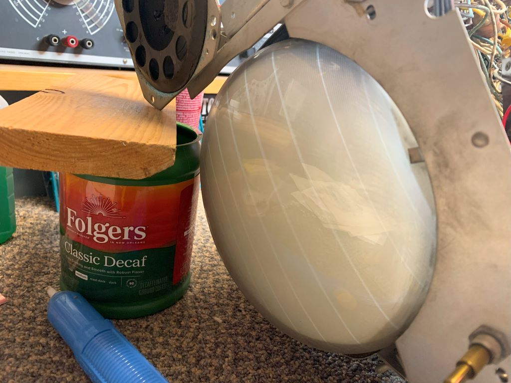
Next, I fired up the B&K 1077 and injected a signal in the antenna. I found the tuner IS passing the signal, although pretty weak. Washed out video, no horizontal hold (vertical seems solid), contrast control has no effect. Next I injected a signal into the 1st IF stage.
***NOTE - VERY IMPORTANT: Mr Anderson mentions in his video that since this is a live b- chassis, you must use an isolation transformer to prevent damaging test equipment or worse. I noted that, but what I DIDN'T think about was how I was powering the chassis for testing. I ran the filament circuit off the power line through a 150w dim bulb for protection, mainly in case I shorted something I wouldn't chance burning up something or worse, blowing the 7JP4 heater! I have been powering the B+ from a variac through an isolation transformer. I can control the voltage and monitor the current easily. So, I connected the B&K and flipped the switch. FULL brightness on the dim bulb! A dead short! Then I realized what I'd done, and the dim bulb did its job, saving my test equipment, picture tube and alerting me that something was wrong! You can never be too careful, and even seasoned guys like me can make mistakes. Please learn from my mistake.
That said, the results of this test were the same. Weak, washed out picture, retrace lines, no H hold. I injected video into the 1 video amp, better but still no H sync, finally the video output grid. The result is below. The video looks solid, NO H sync whatsoever. On the good, vertical sync is solid, and I get sound (with hum) at the tuner and video IF.
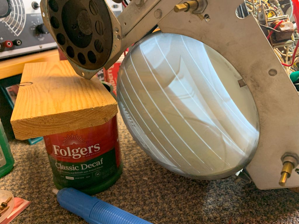
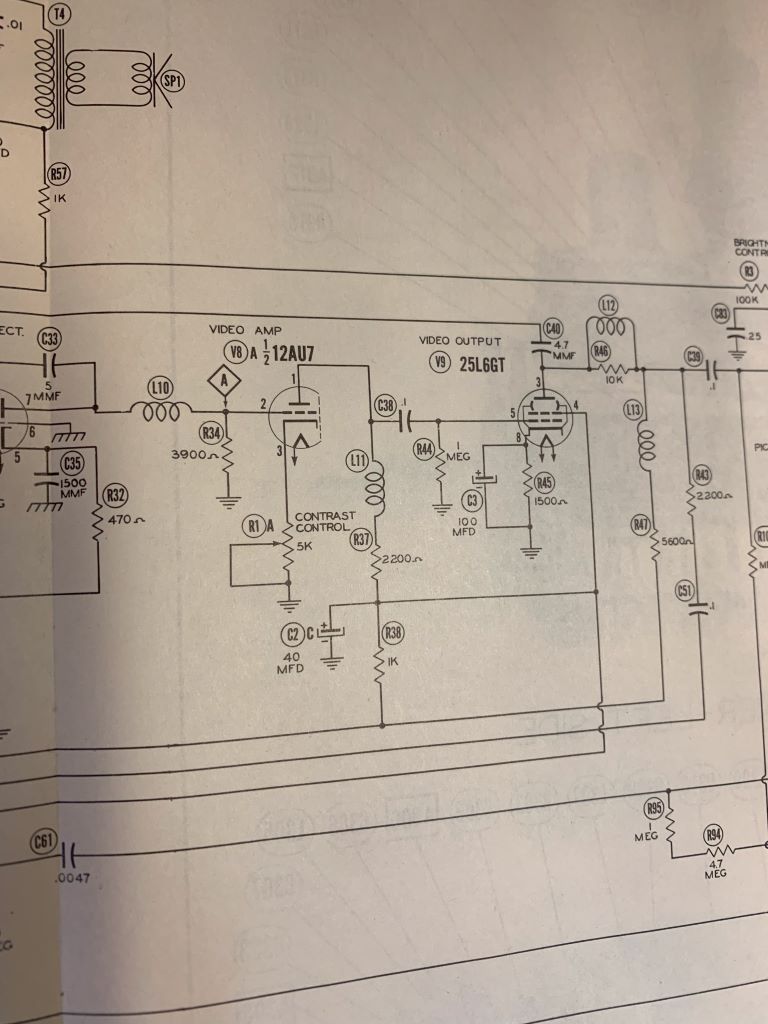
Alright, is the problem in the video amp? I have sync issues too. So, time for some voltage checks. Plate of the video out? Perfect. Full 85v. Grid? Fine to a little high. Screen grid? Ah ha! Should've been 120v, I had about 80v. Checking the 1st video amp, plate was low too. I knew my B+ was at a full 130v, yet on the other side of that 1K resistor was only 80v. I also noted that while not smoking, I could see wet looking wax. Do you see the culprit in the schematic below? Uh huh. C2, 40uf. Probably leaky. I also noted that the same B+ line off that cap also feeds the horizontal oscillator, which is very likely wrecking my H sync. Anyhow, I spent the next evening studying replacement of that can. Not gonna happen (without a bunch of work)! That baby is buried! But I did find I can clip the pins off and relocate the replacements in a nice open part of the chassis, and down in the power supply area. I'll jump back later in with the results. But I bet that wakes up my video and hopefully the H sync.
If I could find the place called "Somewhere", I could find "Anything" 
Tim
Jesus cried out and said, "Whoever believes in me , believes not in me but in him who sent me" John 12:44
(This post was last modified: 01-25-2025, 04:15 PM by TV MAN.)
Posts: 1,222
Threads: 86
Joined: Jan 2014
City: Annapolis, IL
State, Province, Country: USA
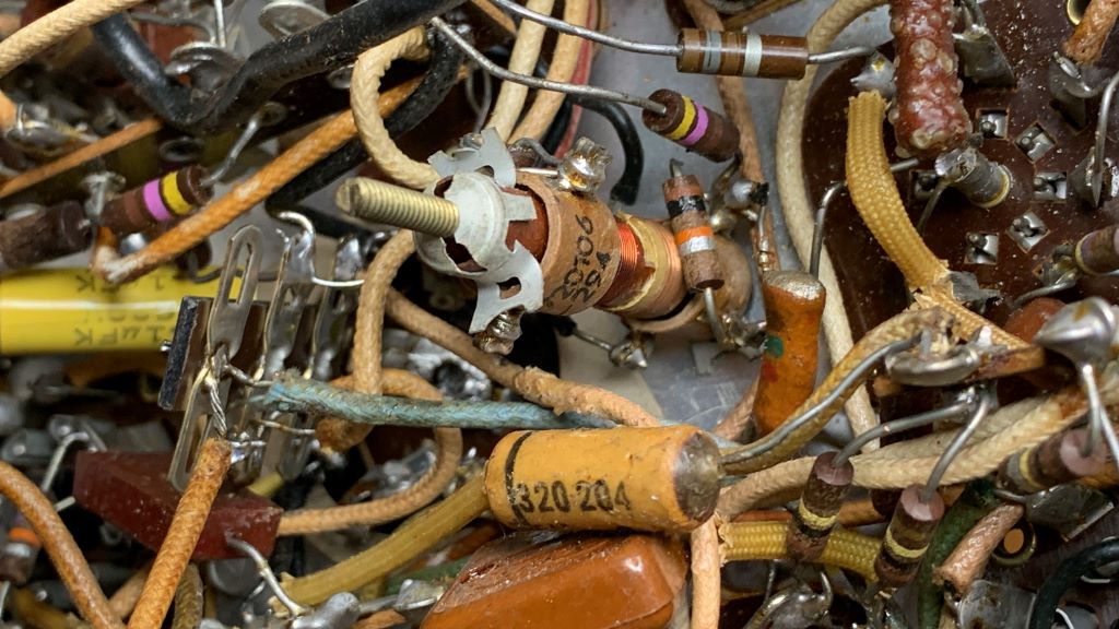
I got some recappin done in the C2 area, which feeds the H osc & Video stage. What a pain! That C2 is buried and has like 20 wires (ok, exagerated some, but ya get the idea)! I didnt just want to clip the pins off the cap - even if I could actually get in there to do it, so I did the diagram, pictures and wire by wire. With all those critical IF and video coils there I didn't want to disturb them if I could avoid. I finally decided on a vertical terminal strip soldered (but not connecting to) the the old caps pins to hold the wires in place. I found a nice open place to put the caps near the vertical section. I don't think there will be a problem doing this. I also replaced a bumble bee cap on the AGC, and a way out of spec resistor feeding the 2nd IF tube. I also replaced that 1k resistor that had been hot and checked at 1.6k. Easy right? Nope, fought that thing for over an hour! Finally got it.
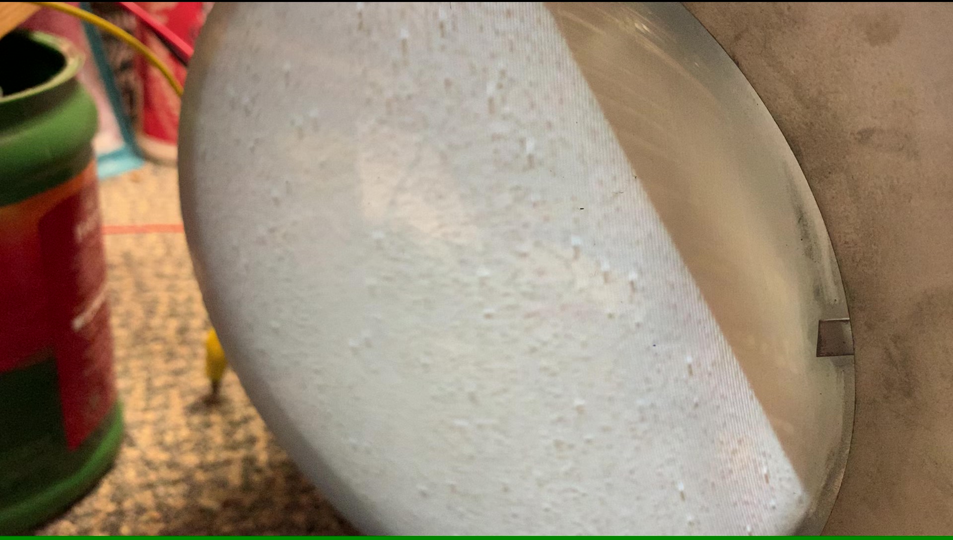
I did a power up tonight and below are what happened when the juice hit! I believe that is snow! A very good sign!
Shot a signal in on channel 4 and ... well, not so great. But, I have horizontal lock now!
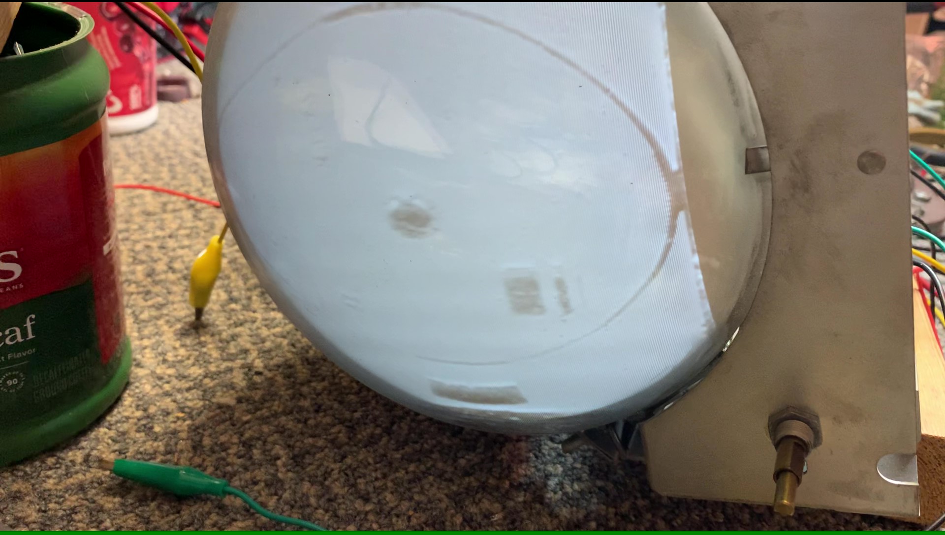
Time to troubleshoot. So, Next I went to the 1st video stage and injected a signal into the grid. This is what I got. Not too shabby!
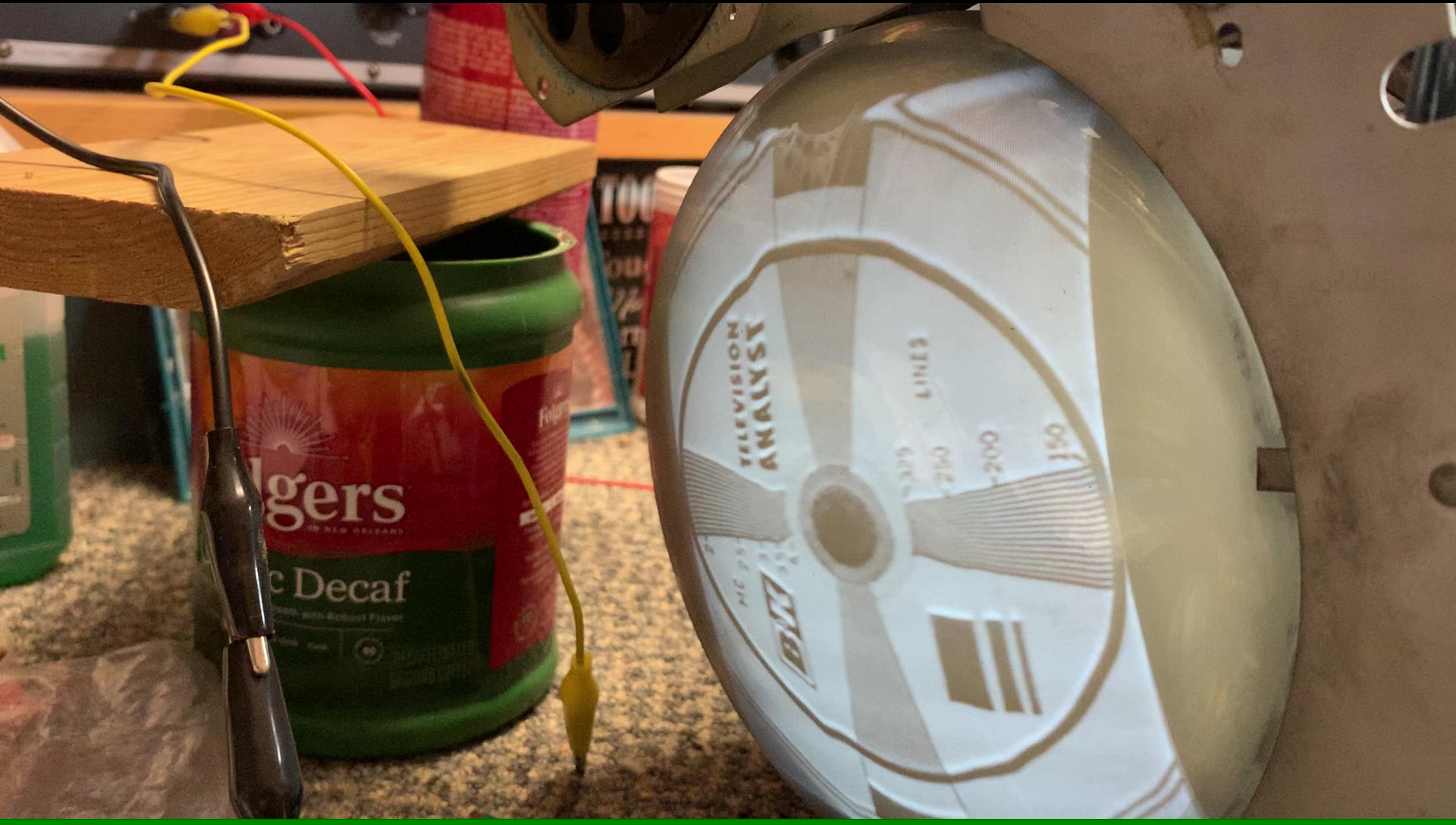
With that working pretty good, I went to the 1st IF stage and injected a signal. This is what I got:
Same. In fact, I can easily overdrive it. I had to back the signal down quite a but is exactly the same as injecting the video stage, so everything is working from the 1st video IF onward. So, I have a problem either with the tuner, possible weak tube, or AGC. Sound is coming through. There's some out of spec resistors on the B+ supply on several IF stages, but if it works ok, I'm probably not going to mess with them so hopefully not to mess up the alignment. I might jump them with another resistor value that will put them in spec and see of that changes anything, but it looks like things are working OK as it is.
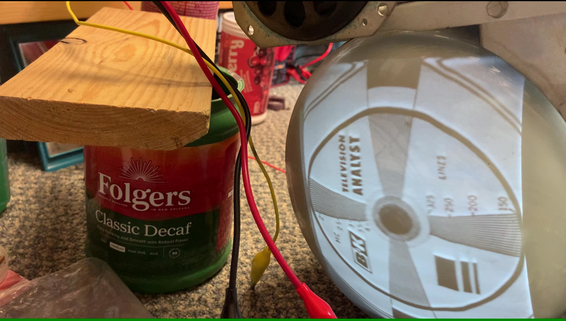
If I could find the place called "Somewhere", I could find "Anything" 
Tim
Jesus cried out and said, "Whoever believes in me , believes not in me but in him who sent me" John 12:44
Posts: 1,941
Threads: 129
Joined: May 2008
City: Omak
State, Province, Country: WA
Hello Tim,
The Picture looks fairly good you, made some good progress !!
Sincerely Richard
Posts: 16,577
Threads: 574
Joined: Oct 2011
City: Jackson
State, Province, Country: NJ
Tim
From your post I understood (leaky cap and such) you did not go with full recap before the troubleshooting.
Wouldn't it be easier to recap, and then troubleshoot?
People who do not drink, do not smoke, do not eat red meat will one day feel really stupid lying there and dying from nothing.
Posts: 1,222
Threads: 86
Joined: Jan 2014
City: Annapolis, IL
State, Province, Country: USA
I know that many would just do the recap - but, something put the set out of service, then if the set has a bad unobtanium part, like that horizontal output transformer, or picture tube (you cant test or rejuv a 7JP4) there's no sense wasting the time or money going further until a part or parts chassis is located. Then, suppose you make a mistake - and the set doesn't work right, where do you start? On a TV, I always do a power up, then go for the the sweep, usually horizontal so as to get light on the screen, power supply then the rest shows itself where to go next. I generally try to do one section or part at a time, then test. If it suddenly shows a problem, then I have a smaller area to look & check over for problems. On a TV, you might drop a blob of solder - say in the audio section that shorts out the B+ to the vertical or video. Well, ya get the idea. So, some may not like my technique, but is how I'm comfortable doing it. It also serves to help me learn symptoms and causes for future projects, then there's the entertainment value 
On something smaller like an AA5, yeah, I test then bring out the shotgun full of caps  But I might not on a big ole Zenith, 10 bands, 4 speakers, 22 tubes packed with layers of capacitors and those cute little strippey black capacitors always covered in oil 
If I could find the place called "Somewhere", I could find "Anything" 
Tim
Jesus cried out and said, "Whoever believes in me , believes not in me but in him who sent me" John 12:44
Posts: 1,222
Threads: 86
Joined: Jan 2014
City: Annapolis, IL
State, Province, Country: USA
Here's tonight's accomplishments. I fed a signal into the tuner and found that I'd made an error in setting the 1077. I didn't realize that when using RF out that the video level also affected the picture! Or I forgot,  , anyway, I was adjusting the the RF level and noted the picture was a lot clearer than last time I'd tried, had a sync buzz in the sound, and realized I had the video output test lead near the set, so I turned the video level down thinking it was making interference - then I saw it! I was overloading the video signal, and when I turned it down, it came in clear as could be! I made a few other adjustments - then realized I was still running the filaments through my 150w bulb! Duh! Senior moment, so I bypassed, connected a set top box - and this is what happened next:
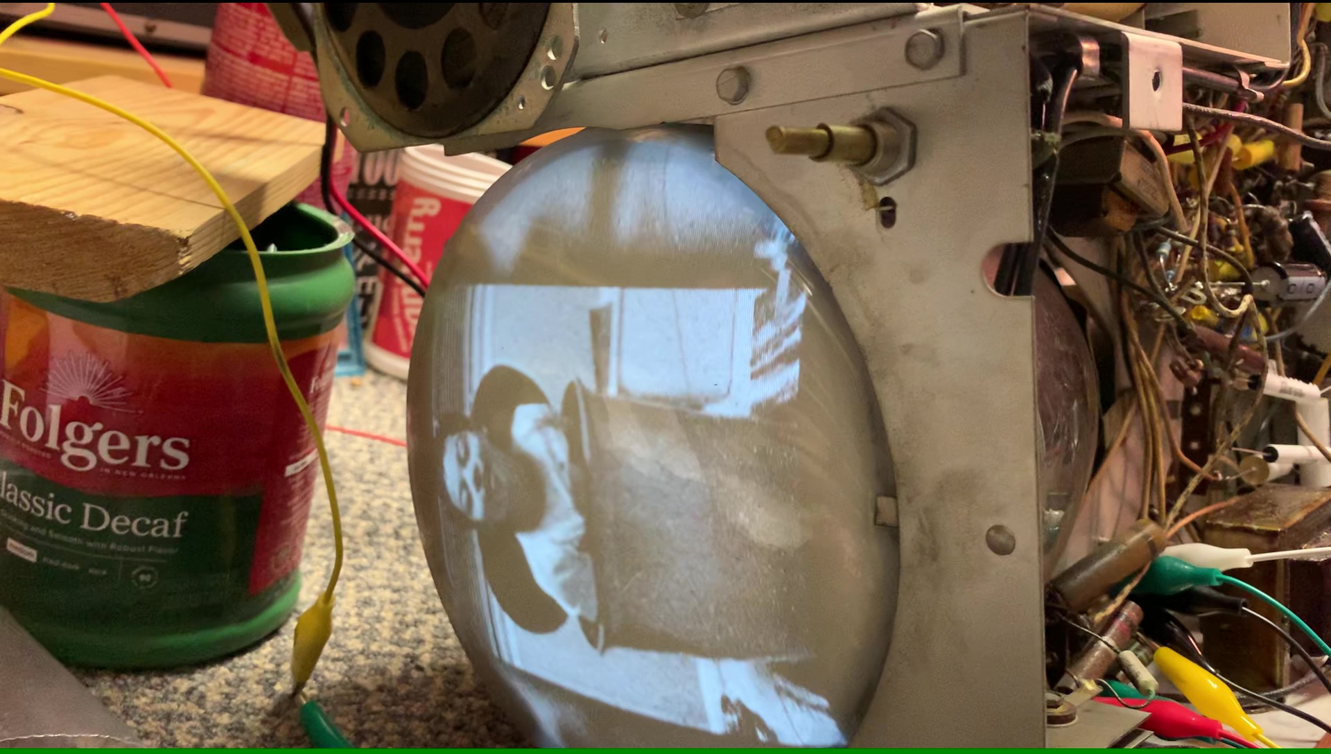
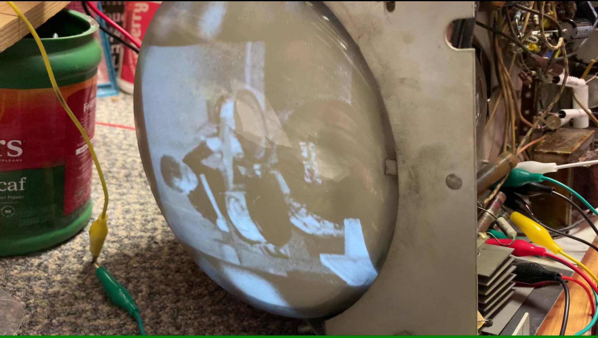
The contrast came to life and so did the clarity! This is only with a Horizontal hold and slight vertical adjustment. Sound is loud, but once I get those last few caps replaced, and a couple more resistors, I will do the final (hopefully) adjustments and do a burn in. I still need to pull the picture tube, clean and replace that cap inside the HV box, but I really didn't want to do that until I had about everything else running good.
A note: Please DON'T in any way take this as me being critical, and I'm sure Mr Anderson would probably agree, but TV work takes a totally different approach and techniques than other equipment, thus should explain why I approach them differently. It takes different test equipment, a different mindset, and different diagnoses. Plus, there are MUCH higher voltages in different areas, so you have to be careful. If you watch some of Mr Andersons or Shango066's videos along with some others, you will find their techniques on TV work is similar to mine. We power up and try to get the screen to light up because that screen is the "window to the soul" of the set we are working on. If there's a bad picture tube, deflection yoke, horizontal or vertical transformer, those are often very critical to the set showing a good picture when finished. If any of those parts are bad, there's no point going any further replacing caps, tubes or spending time until the right parts are located, or the decision is made to use the set for parts, or ... dumpster. 
If I could find the place called "Somewhere", I could find "Anything" 
Tim
Jesus cried out and said, "Whoever believes in me , believes not in me but in him who sent me" John 12:44
Posts: 1,222
Threads: 86
Joined: Jan 2014
City: Annapolis, IL
State, Province, Country: USA
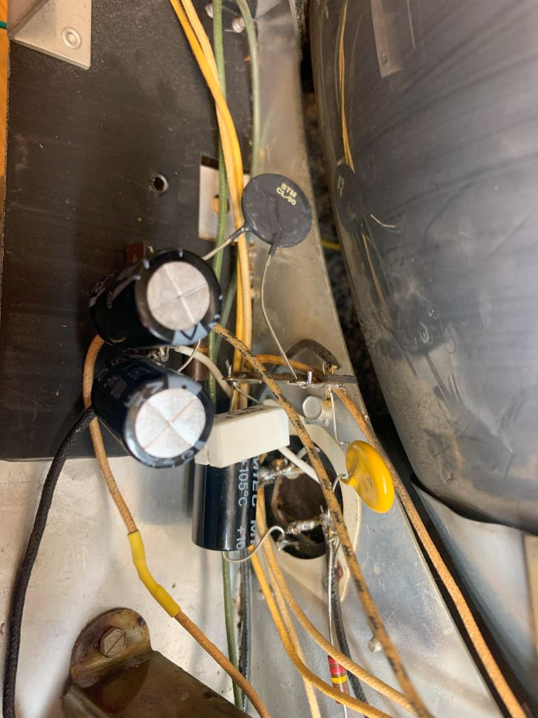
Today I got some final (I hope) work done. I know there are some that absolutley blast me because ... "WHY don't you just recap everything and it will work fine" folks. Uhmmmm... follow me and you will see just WHY. So, today I 'finished' the power supply, neated it up, added a CL90 (probably too big). I moved the heater wire to the other side of the CL so it would be softened on start up.
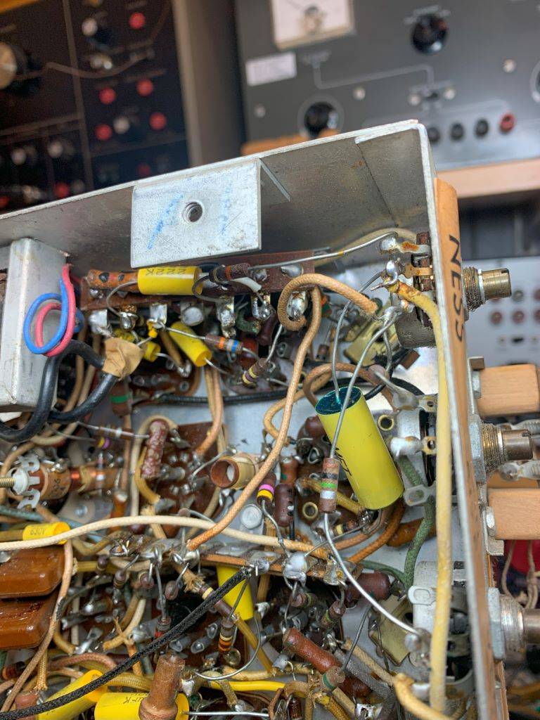
Next, I finished the recap on the audio section. Replaced the coupler, decoupling cap and another. Done.
I powered up to check things and this was the result:

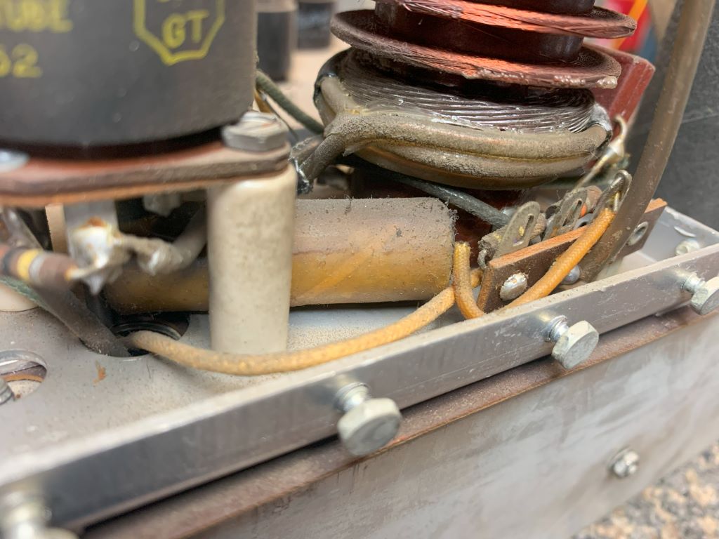
I discovered a hum bar going up the screen and after some checks (think) found it was coming from the inrush current limiter, so I bypassed. Set works great for about 5 minutes then the HV drops off and pic goes to crap. So, next step - replace the cap inside the HV box that I suspect. That means pulling the big tube. It's ok, I want to clean things and test the tubes.
Before:
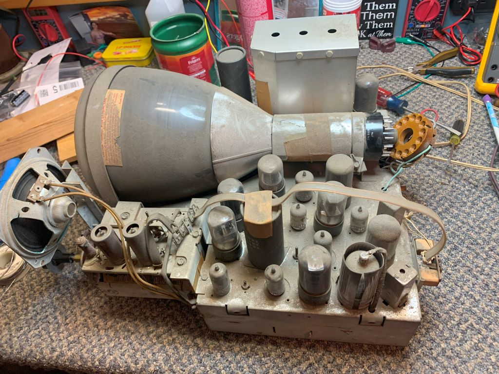
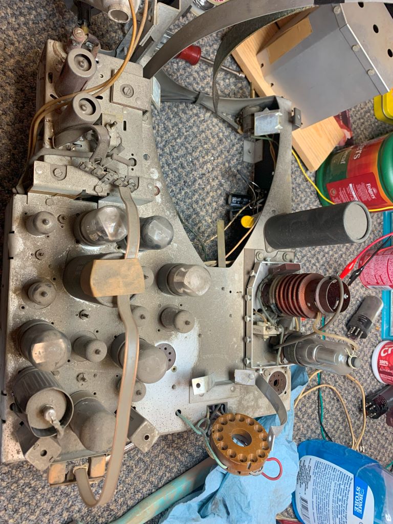
Tharez that lousy cap that is probably killing my HV.
If I could find the place called "Somewhere", I could find "Anything" 
Tim
Jesus cried out and said, "Whoever believes in me , believes not in me but in him who sent me" John 12:44
Posts: 1,222
Threads: 86
Joined: Jan 2014
City: Annapolis, IL
State, Province, Country: USA
I needed to loosen the HV tube socket, so that meant removing the 1B3. The getter looked ok, so I'll reuse the tube. I can replace if needed by simply removing the top of the HV box. Well, here's what happened next: SNAP!
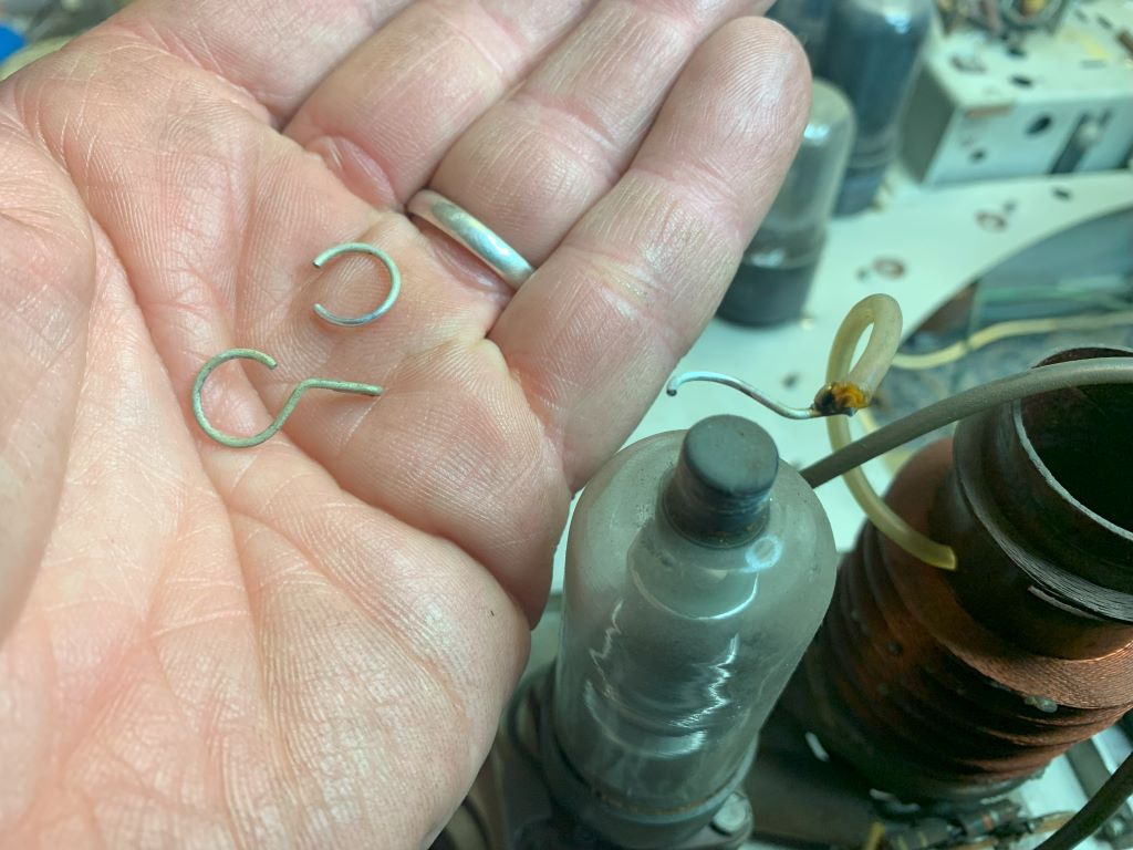
So, after replacing the cap and HV tube plate connector.
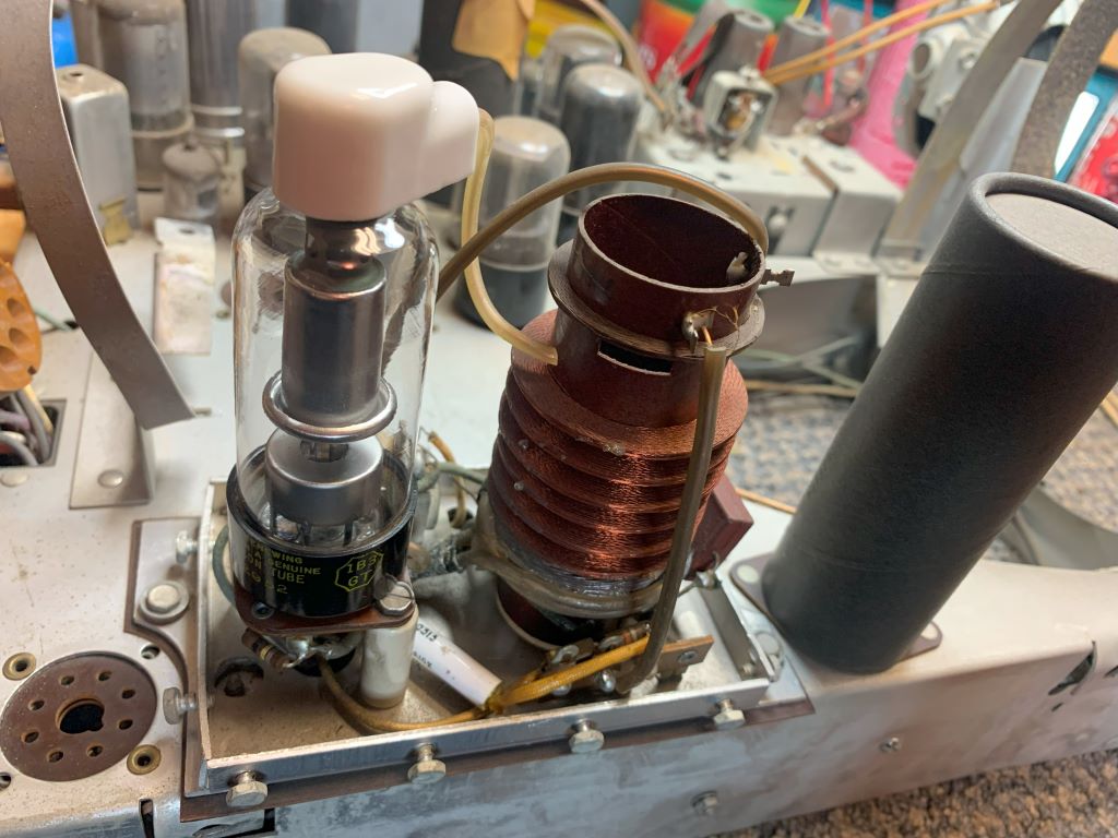
The cleanup and tube testing:
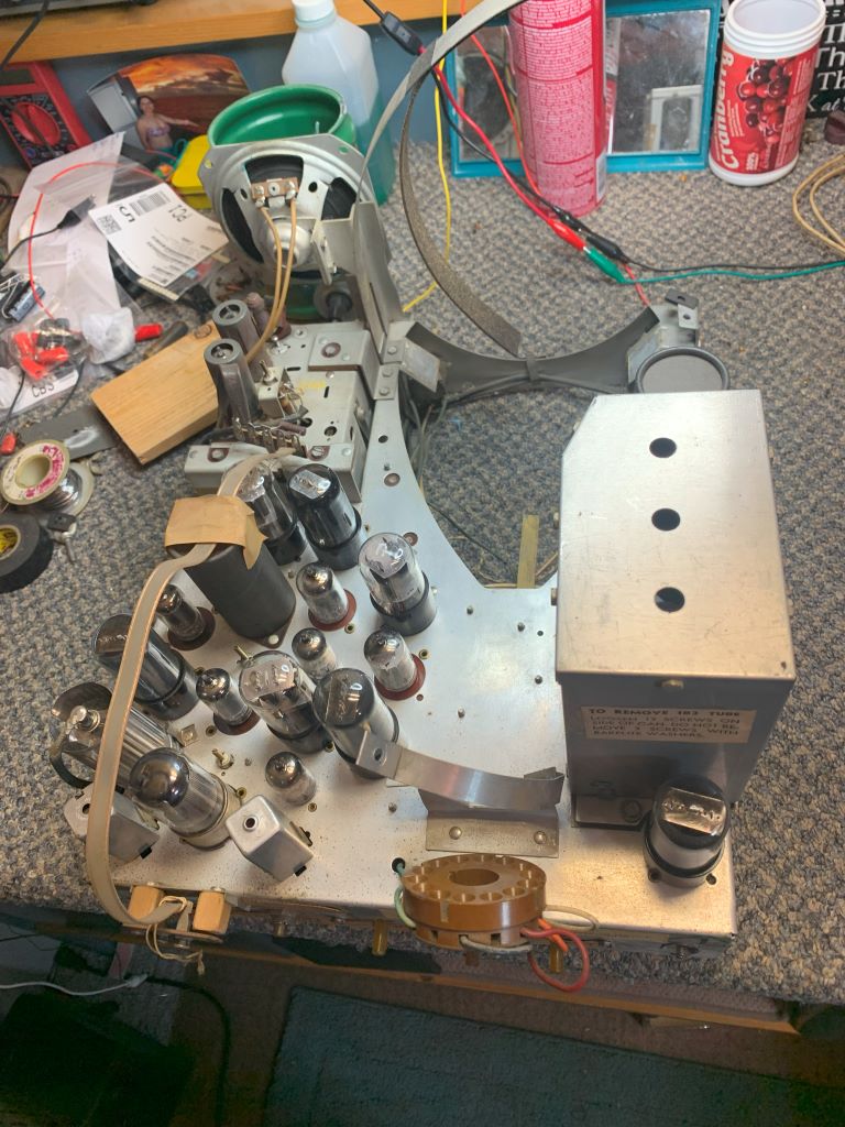
Done! All cleaned up, tubes tested and back in their proper sockets, time to do a test. I did find a couple weak 12AU7A tubes, but if they work ok - I'm leaving them. Just making a note. All others tested and all original Emerson tubes except the horizontal output 25L6 tube, which was a GE.
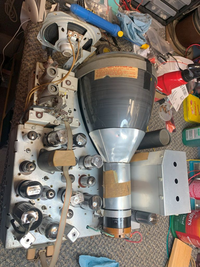
Turned out quite nice! Or DID it??? So, time for a power up and some adjustments. Power applied - and - NOTHING! Tubes light, DEAD otherwise! What?! So I flip the chassis and power up to make some checks and look for smoke. Nothing! B+? Yup! HV? Yup, nice solid 5kv. No sound, no light on the screen! Turn off and set up for more checks, power up and - even NOTHINGER! (Not a word I know), but follow me. Ok, so this time only half my tubes were lighting up. Wiggle, shake, tap - nothing, so test time. After about the 6th tube I found the heater on a 12AU7 open. Dang! I NEED that inrush limiter! May just have to tolerate some hum to keep my tubes alive. Was that the problem? Nope! Still nothing! No buzz in the sound when I touch the volume control, no light on the screen, all tubes have plate and screen voltages. Dead - dead - dead. . What did I DO? I've been here before - with a decent working something or other, then clean and check and it quits! Sometimes I think it is better to clean what you can and leave it alone! Well, stay tuned 'cause this set WILL come back to life if I have to bring it back one tube at a time!
If I could find the place called "Somewhere", I could find "Anything" 
Tim
Jesus cried out and said, "Whoever believes in me , believes not in me but in him who sent me" John 12:44
Posts: 1,941
Threads: 129
Joined: May 2008
City: Omak
State, Province, Country: WA
Hello Tim,
Yes, don't you hate when things go like that and go snap ?
Anyway lots of progress on your tv .
Sincerely Richard
Users browsing this thread: 1 Guest(s)
|
|
Recent Posts
|
|
Philco 42-345 Restoration/Repair
|
| Ok MrFixr55,
I have tried the DeoxIT D5 on the band switch and even though it has relieved the tension I felt when turn...osanders0311 — 11:11 AM |
|
Part numbers to model cross
|
| Is there a reference somewhere where you can punch in Philco part numbers and see what models those parts were used in?Jim Dutridge — 10:17 AM |
|
Philco 42-345 Restoration/Repair
|
| Hi OSanders,
Look carefully at the band switch. Turn it slowly and "wiggle" it around the desired band. ...MrFixr55 — 12:33 AM |
|
5U4 vs 5Z4 tubes
|
| I think that RCA and GE introduced metal tubes in the USA in 1936. I don't know if they were being made by RCA, GE or b...MrFixr55 — 11:20 PM |
|
Philco 42-345 Restoration/Repair
|
| Vlad95,
Thank you for the stringing guides and wow there are so manyosanders0311 — 06:01 PM |
|
5U4 vs 5Z4 tubes
|
| A pre war Hallicrafters, and an early one too, very nice! 1936 is pretty early for metal tubes too, which would explain ...Arran — 05:58 PM |
|
Philco 42-345 Restoration/Repair
|
| Thanks Rod,
"When you hear the background hiss and no station it usually indicates that the oscillator quit" ...osanders0311 — 05:52 PM |
|
Philco 42-345 Restoration/Repair
|
| RodB
:beerchug:Vlad95 — 10:22 AM |
|
Philco 42-345 Restoration/Repair
|
| Vlad, you nailed it. Swiss and German roots.RodB — 09:54 AM |
|
5U4 vs 5Z4 tubes
|
| Well this is a Hallicrafters SX/9 circa 1936.
No real issues so far although I dodged a real bullet with a cap that was...bridkarl — 07:59 AM |
|
Who's Online
|
There are currently 1840 online users. [Complete List]
» 2 Member(s) | 1838 Guest(s)
|
|
|

|
 
|


![[-] [-]](https://philcoradio.com/phorum/images/bootbb/collapse.png)


