Posts: 1,929
Threads: 127
Joined: May 2008
City: Omak
State, Province, Country: WA
Hello morzh,
man that set is got dusty chassis and it is funny that dial looks like the same style that is on my Zenith model 755 .
that chasis is the size of one their early Tv's and I bet it weights like one too.
One thing I like about bakelite blocks you can easly hide your new capacitors and they are fairly easy to do .
The cabinet looks in fairly good shape thou.
Sincerely Richard
Posts: 16,559
Threads: 573
Joined: Oct 2011
City: Jackson
State, Province, Country: NJ
First and foremost, this chassis is a back-breaker.
Then, it has that big capacitor block, which I hate, and which is the 3rd one I am dealing with (111 and 86 were the first two, and I still have not defeated the latter).
I never have seen a schematic with so many discrepancies between it and other schematics (like I said, I see 3 versions now, the one in our repository, and two (earlier and later) in Riders, and this is without the fact the Nostalgia version has no values in it).
I still have no parts list from any of the document. Maybe someone knows where it is.
And I wonder why Rider's made a piecemeal out of it, having 1-sheet sch in 1st book, the chassis photo in another, and the alignment procedure in yet another one.
I had no such problem with 111, 112 or the 86.
The Philco was modified during the Philco times, or at least by some Philco repairman.
All parts used in repairs/mods are Philco, and are time-appropriate. That 5K resistor on the capacitor block that should be 13K: yesterday I de-soldered it, and the soldering was as factory as it gets.
Also, there is an original tubular Philco 0.015uF cap (200V; I would use at least 400V at the time) that is not on the sch, not in the chassis' photo, but is soldered from one of the AC line wires to the chassis (a Y-cap).
I checked the volume pot; it is bad. End-to-end is a few Megaohms. I believe I changed it in 111; I will have to do the same here.
The tone control...well, I have tons of experience rebuilding these (it is yet to be dealt with).
People who do not drink, do not smoke, do not eat red meat will one day feel really stupid lying there and dying from nothing.
Posts: 16,559
Threads: 573
Joined: Oct 2011
City: Jackson
State, Province, Country: NJ
Today finished resistors (Mouser came) and tone control.
The tone control in 96 is the same as in all similar radios: 95, 111, 112 and even 90.
Unlike the metal version, this one does not allow to pull or push the caps compartment out, so it had to be picked out after some heating. Not bad at all.
I was able to reuse the wires that went from the contacts to the caps.
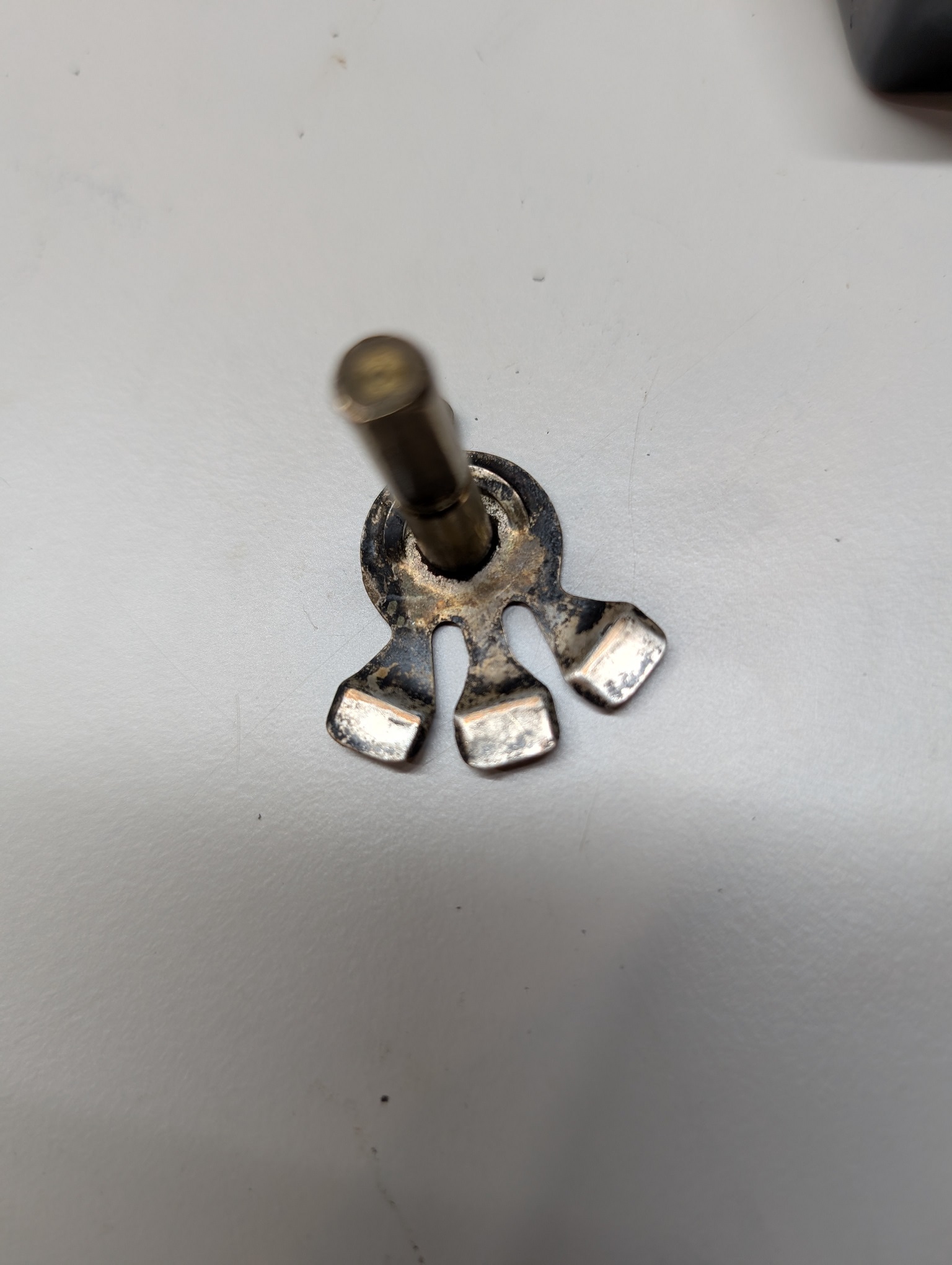
The tone ctl was dirty. I took it apart, as I knew I would have to clean the contacts.
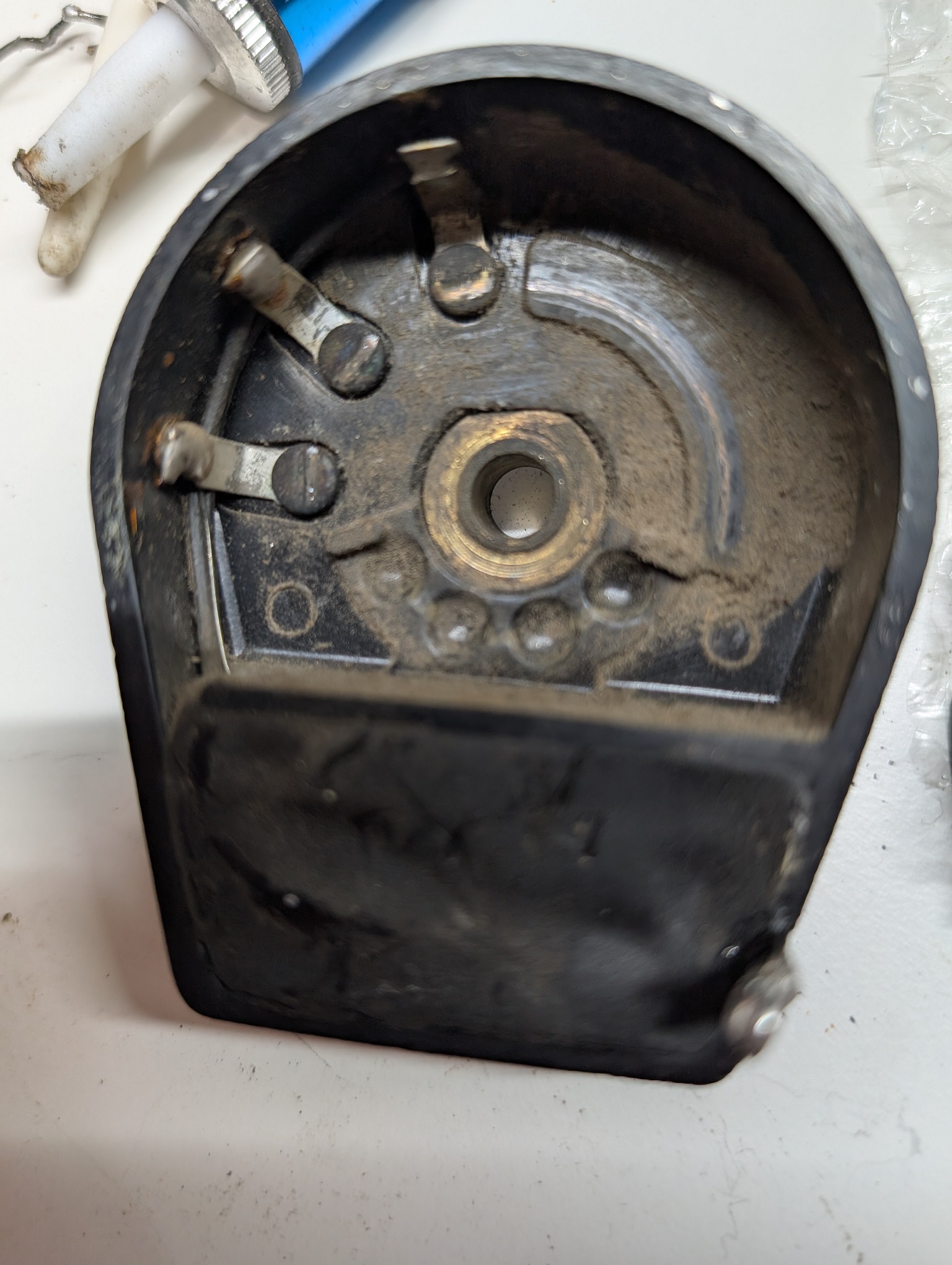
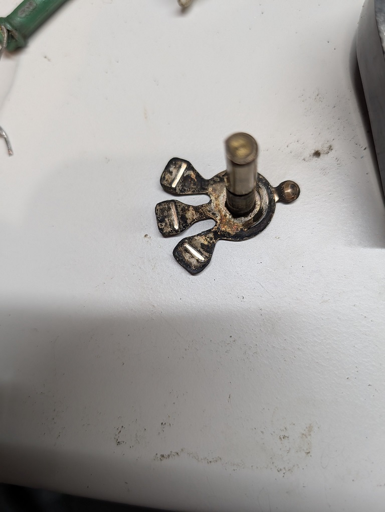
Then pried out the caps.
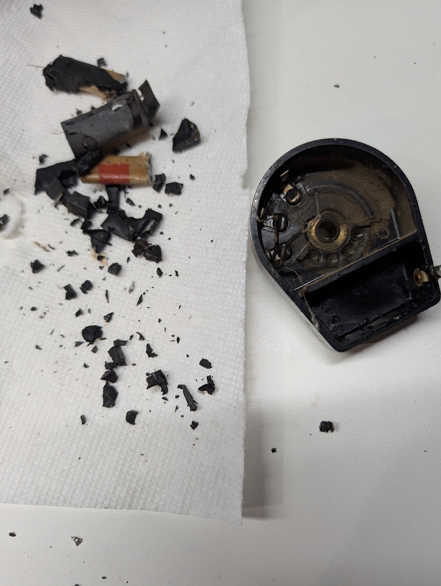
Cleaned the case and the contacts
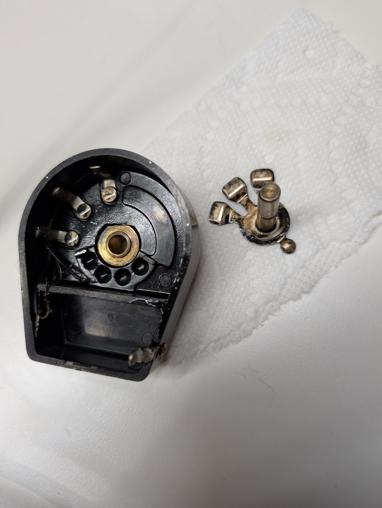
Then prepared the assembly from three caps: 15nF, and 2x10nF.
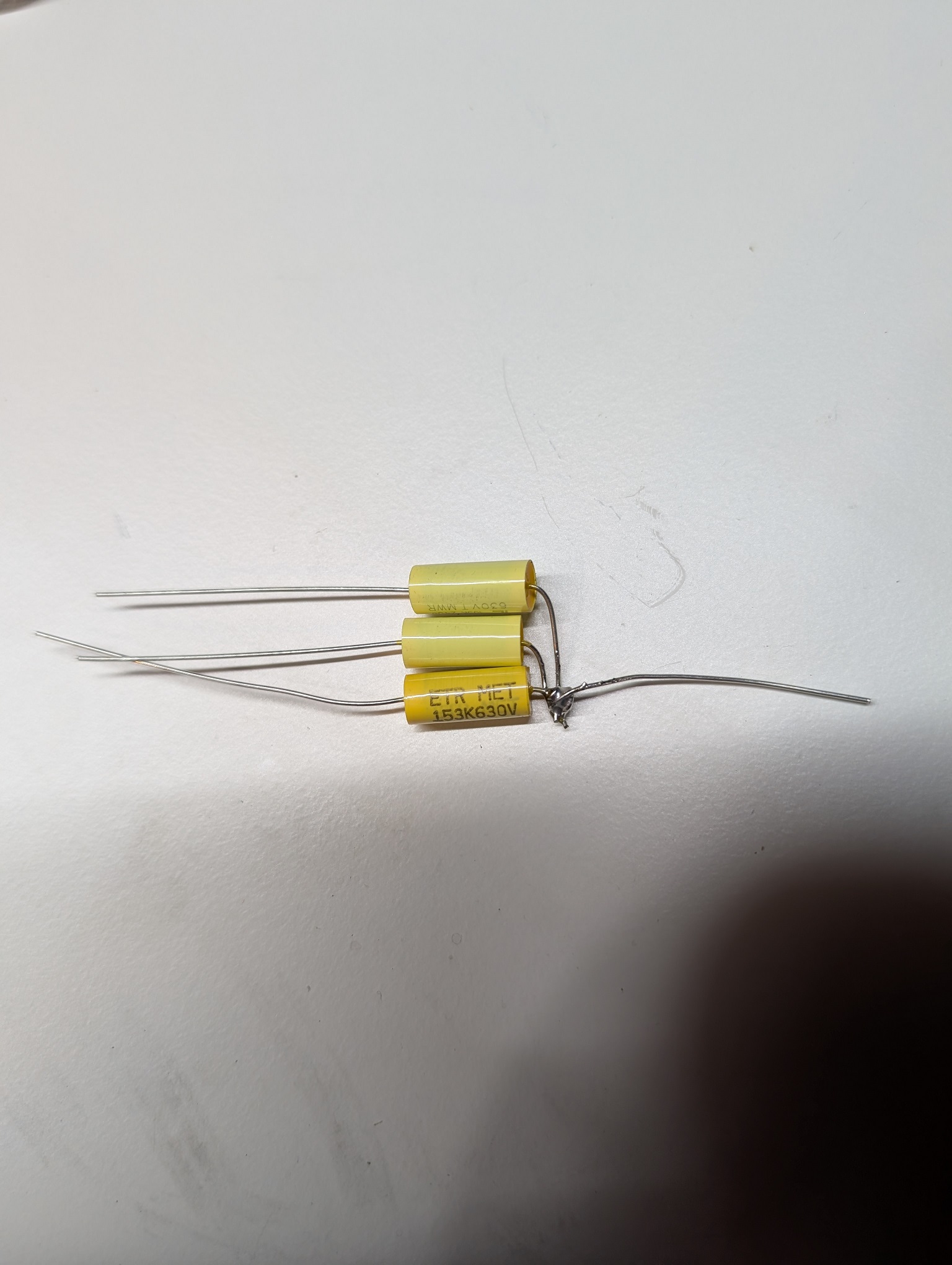
As I said, I was able to re-use the wiring. I lined the bottom with fish paper. Even though the case is backelite and there is no fear of the case shorting things out. Just felt right.
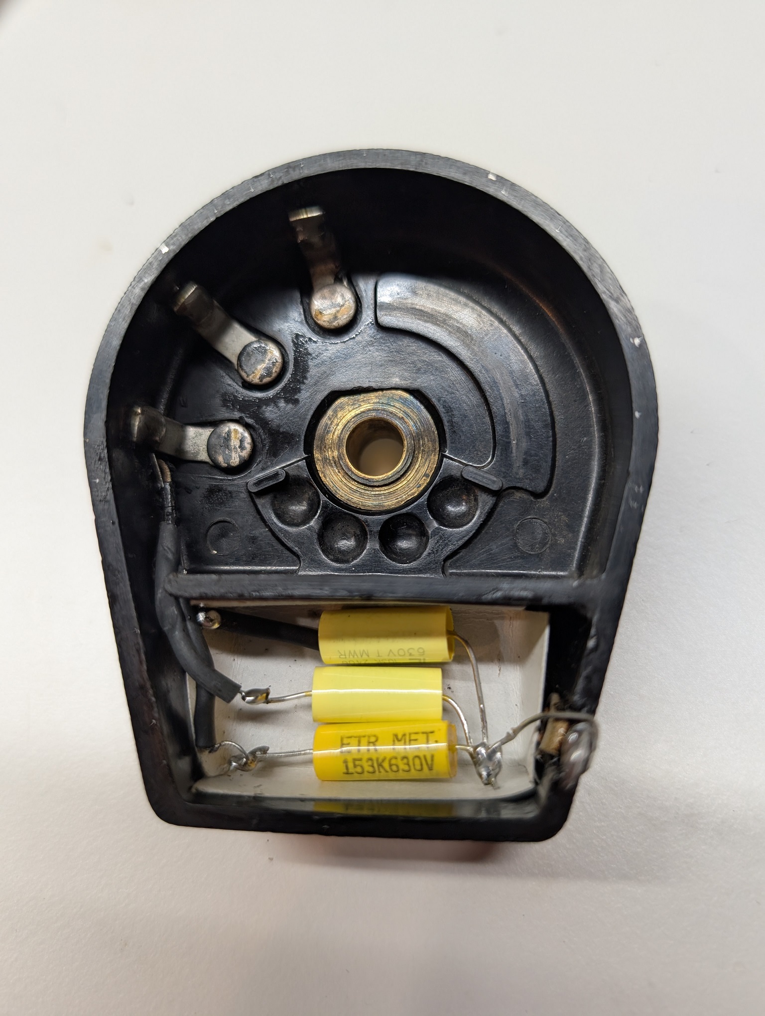
Made a cap from fishpaper, to keep hot glue from damaging film caps. Yes, I know, some folks here stated this is safe to pot them directly, but then it costs me nothing and puts my mind to ease. I also used eraser on my pencil to clean the contacts a bit more, as somehow my usual method, IPA, did not clean all of the deposits. Then washed with IPA again, as rubber, if not washed off silver, will blacken it over long term due to the sulfur present in it.
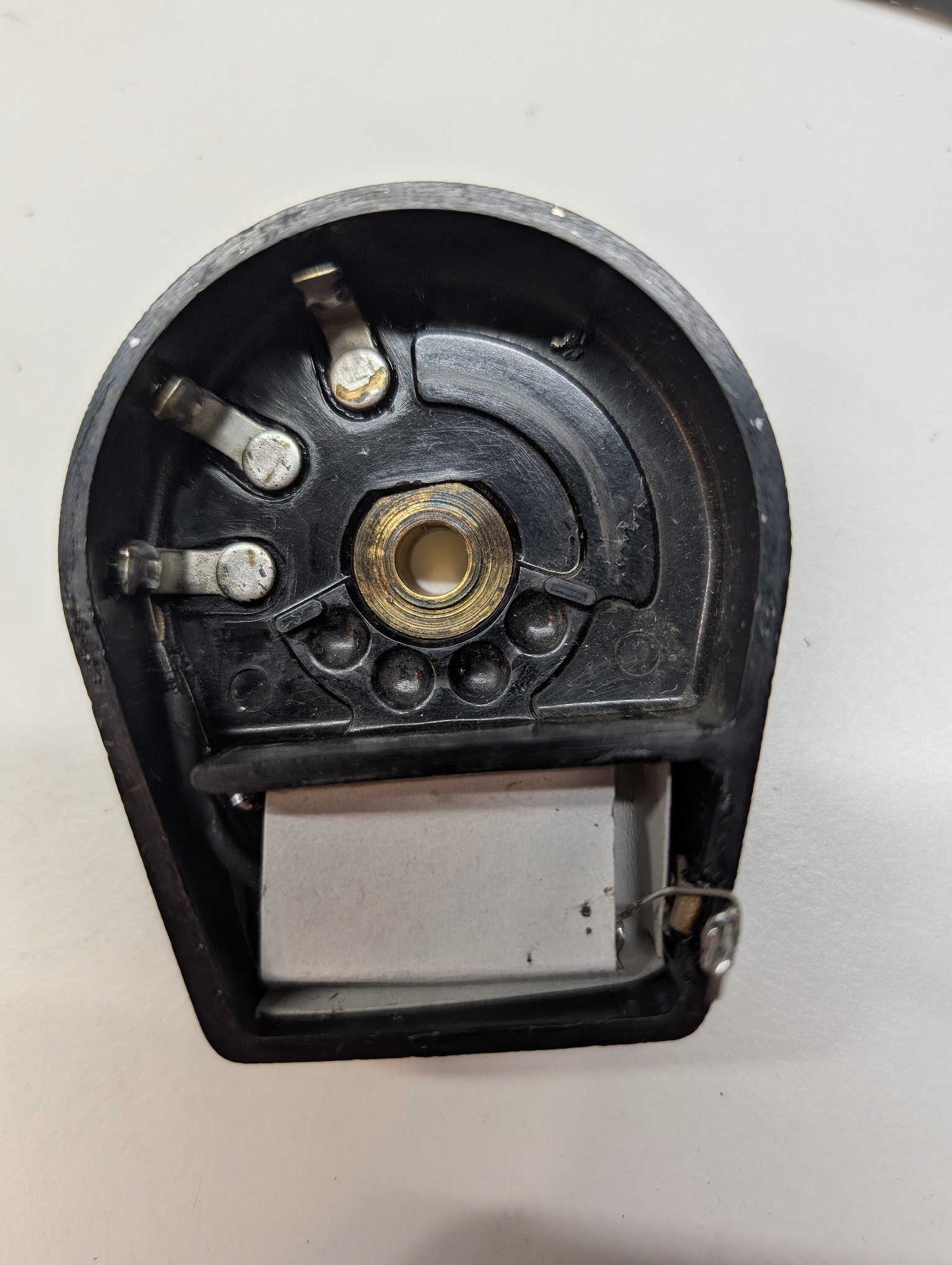
Then I potted.
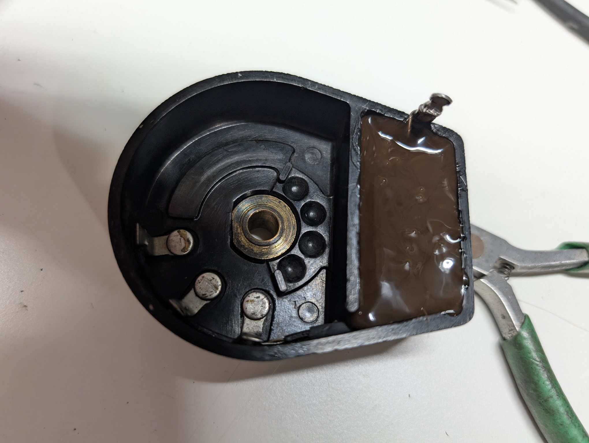
This is the Tone Control
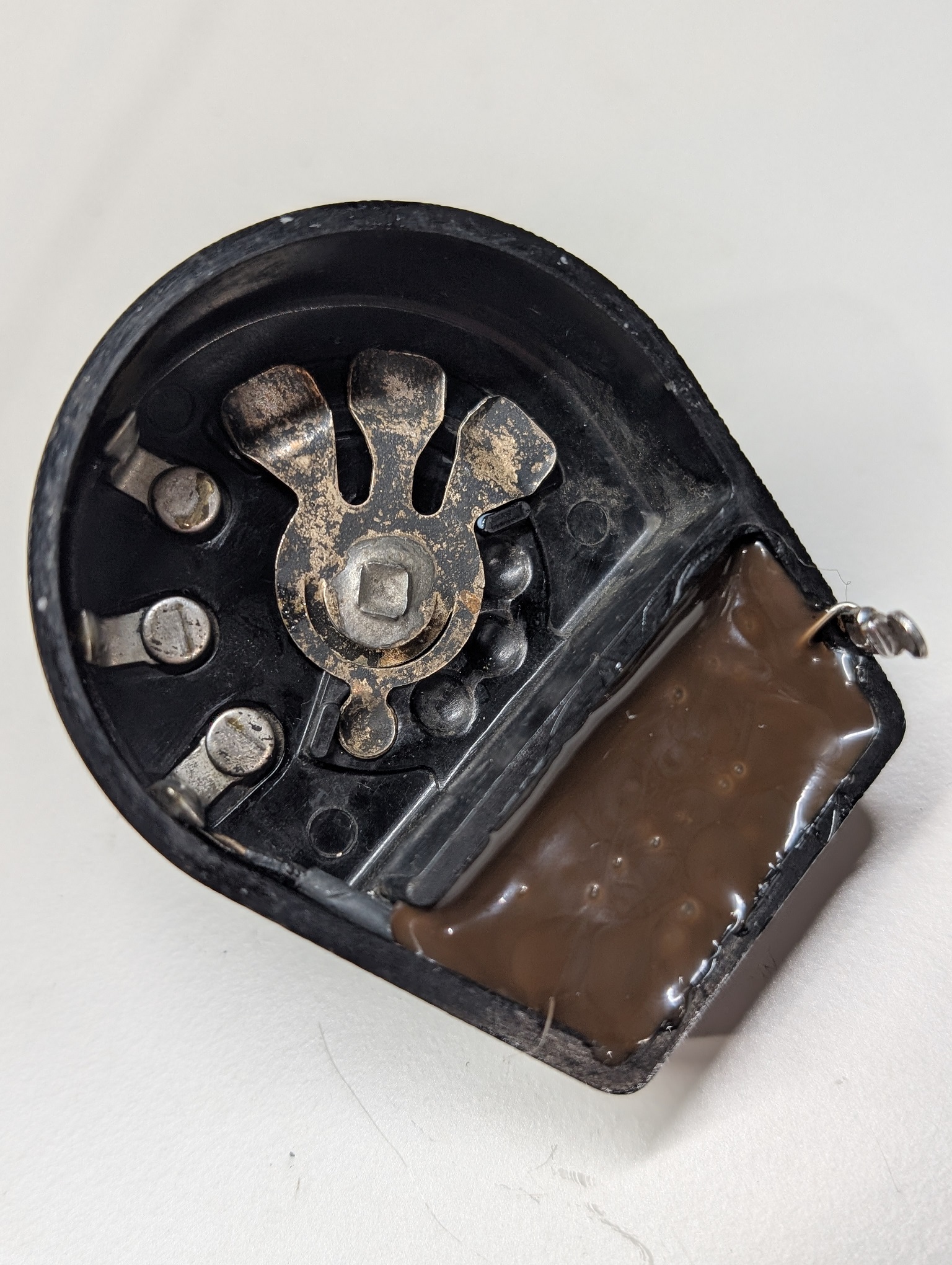
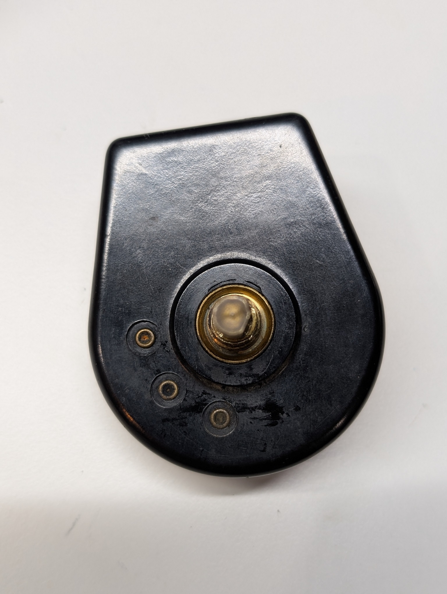
And installed it back.
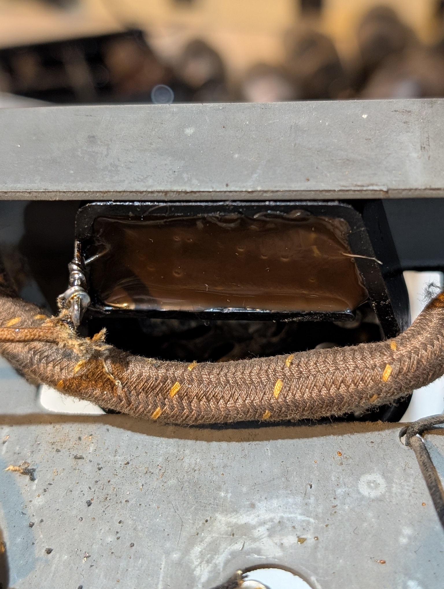
People who do not drink, do not smoke, do not eat red meat will one day feel really stupid lying there and dying from nothing.
Posts: 4,927
Threads: 54
Joined: Sep 2008
City: Sandwick, BC, CA
How did I miss this thread? I own a model 96 (lowboy cabinet), Mike is fixing up a model 96 and I didn't notice until today even though the thread started on January 12. With regard to the speaker in mine, the field coil is good but I think the audio output transformer is not, as usual the audio interstage went bad, and was replaced decades ago, but the Hamond replacement went bad also. I think that the main difference between a model 95 and a model 96 is that the latter incorporated an early form of AVC/AGC, which is pretty good for a 1930 model TRF set.
Regards
Arran
Posts: 16,559
Threads: 573
Joined: Oct 2011
City: Jackson
State, Province, Country: NJ
Arran
As far as I could tell, there's no such difference between 95 and 96.
They are essentially the same radio, and the differences are minor.
96 has tone control, 95 does not.
95 has long distance switch, 96 does not.
Schematics-wise, this is it.
Otherwise, 96 used backelite capacitors, and the 95 used tubular capacitors.
People who do not drink, do not smoke, do not eat red meat will one day feel really stupid lying there and dying from nothing.
Posts: 7,305
Threads: 270
Joined: Dec 2009
City: Roslyn Pa
The speaker plugs are different...
When my pals were reading comic books
I was down in the basement in my dad's
workshop. Perusing his Sam's Photofoacts
Vol 1-50 admiring the old set and trying to
figure out what all those squiggly meant.
Circa 1966
Now I think I've got!
Terry
Posts: 16,559
Threads: 573
Joined: Oct 2011
City: Jackson
State, Province, Country: NJ
Yes.
Both speakers are G-type, but 96 has the same type as 20/90, and 95 has the older style, rectangular that plugs on top of the chassis (well, they both are on top).
But I was talking about circuit differences only.
Because there is also difference of the dials (brass/plastic (celluloid)) and such.
People who do not drink, do not smoke, do not eat red meat will one day feel really stupid lying there and dying from nothing.
Posts: 16,559
Threads: 573
Joined: Oct 2011
City: Jackson
State, Province, Country: NJ
Have just found Ron's responce to mg34.42 from 2022.
"Ok. Differences:
Model 95 has a brass dial scale, illuminated from above; Model 96 has a tan celluloid dial scale, illuminated from behind.
Model 95 has a two position local-distance switch; Model 96 has a four position tone control.
Model 95 uses the 1928-29 cylindrical capacitors under the chassis; Model 96 uses Bakelite block capacitors.
(I think) Model 95 uses the older 1929 speaker connector with four pins spaced wide apart - a large rectangular plug; Model 96 uses the "newer" speaker connector which is the same as used on 1931 Philcos such as models 70, 90, 112, etc. - a round plug with four pins spaced closely together, much like a 4-pin tube base, only with one large pin.
And that's about it. Icon_smile They are otherwise the same. "
People who do not drink, do not smoke, do not eat red meat will one day feel really stupid lying there and dying from nothing.
Posts: 1,929
Threads: 127
Joined: May 2008
City: Omak
State, Province, Country: WA
Hello morzh,
That is good to know !!
Sincerely Richard
Posts: 16,559
Threads: 573
Joined: Oct 2011
City: Jackson
State, Province, Country: NJ
Found another typo in Ray's capacitors book.
The cap between lugs 5 - 11, the one connecting the centertap to GND, is shown 0.15uF.
In all sch it is 0.015uF, and is also the same in 95 and 111 sch.
I took the cap meter to it, as most caps kept their functionality, with capacitances going 2x up, so 2uF would be 3.5uF, 0.5uF goes to 1uF and so on. This cap went to 0.04uF, eventually going just under 0.1uF; this tellsl me the 0.15uF value is the correct one.
People who do not drink, do not smoke, do not eat red meat will one day feel really stupid lying there and dying from nothing.
Posts: 4,927
Threads: 54
Joined: Sep 2008
City: Sandwick, BC, CA
I have a copy of a schematic where the capacitor, and resistor values were written in, and I think it was one that Ron Ramirez made a few years ago, it shows the values of the cap in the big condenser can. Yes, I'm pretty sure that the majority of the Bakelite blocks are .015 uf, in a TRF set there would be a lot of repetition since it's basically a cascade of tuned circuits, one after the other, with a detector thrown in.
Regards
Arran
Posts: 16,559
Threads: 573
Joined: Oct 2011
City: Jackson
State, Province, Country: NJ
I opened up and lubed the volume pot.
It is suposed to be 500K (no one expects it to be that), and it is about 1.5M.
The contact of wiper and the resistive band has improved after F5 application.
One thing I am not sure: it looks like the taper is linear and not log. I am not familiar if the log taper was used back then: even in Philco 20 the pot is wirewound and therefore is unlikely to be log taprer.
So is it linear? Anyone knows for sure?
Also, the power switch. Open, after 5-10 clicks going to 100 Ohm or so...
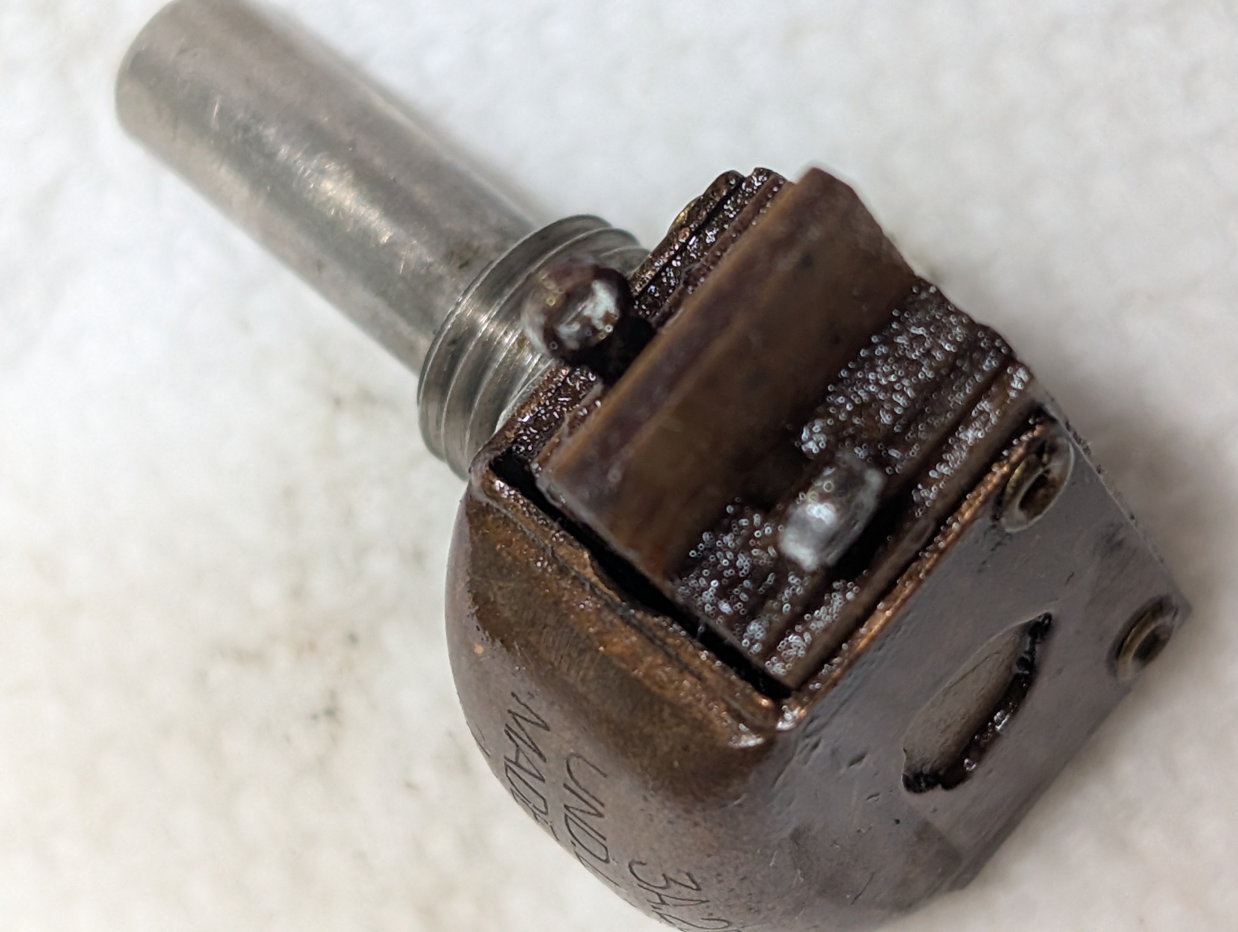
A narrow opening right between the copper dome and the rest of the case could be seen in this photo; I icould see some movement through this slit; I sprayed D5 into it, twice, and worked the switch.
It is now dow no 0.3-0.5 Ohm.
I will dry it and replace.
People who do not drink, do not smoke, do not eat red meat will one day feel really stupid lying there and dying from nothing.
Posts: 16,559
Threads: 573
Joined: Oct 2011
City: Jackson
State, Province, Country: NJ
Spraying Deoxit inside did the job; today it was dry and still showing 0.25 Ohm when the switch is made.
So, I put it back, and then realized I have yet to check the tubes.
The very first tube, the 80, was near-dead. That might be the reason why the radio was retired. It barely showed any conductance.
Luckily, I have a truckful plus a small wheelbarrow of 80s.
The rest of the tubes were OK or good; the output 45 both are, let's puit it that way, not too strong. One is 900, another 700 on Hickok 600A, and the new tube is 1,850. But I figured they would work. Plus I have no choice: I got no 45 in my stash.
Then I tested the interstage transformer, which was not an original: it was OK.
Then I tested the AC, which was fine.
Then I put the tubes in and tested the rectifier, which was also fine.
Then I pulled out the Philco 20 speaker, which electrically is very much the same as the G speaker: a pushpull transformer and 3100 Ohm Field coil. And exact same plug.
I put 110VAC to it, and, after turning off the light (which creates interference) I attempted to go and receive the local station, without an antenna, while being at the basement. To my surprise not only I received the local station, but many stations on the way to it. This is, again, with no antenna and without an alignment having been performed.
I shot the video of all this: this is the link to the Youtube.
https://www.youtube.com/watch?v=1GHHfd_Rjuo
People who do not drink, do not smoke, do not eat red meat will one day feel really stupid lying there and dying from nothing.
Posts: 16,559
Threads: 573
Joined: Oct 2011
City: Jackson
State, Province, Country: NJ
Today I decided to take on gutting the big bad cap block.
I gave up on the same one from the 86 before, so I was not sure: the score was 1:1 when I successfully gutted the one from 111 but failed with the one from the 86.
So first I put it on two wood blocks, covered the table with aluminum foil and blasted the can from two heatguns set on Hi.
After 10 minutes I saw no movement induced by gravity. Later I undersrtood why.
Then I took that huge screw I bought over 10 years ago for this exact purpose, and tried to pull the guts with the bolt held with vice.
Nope.
Evebtually I realized I would have to pick at it with screwdriver.
I covered the table with saran wrap, and, using a very large (old, probably 70 years old), square cross-sectioned flat screwdriver, took away the tar from the top.
Then something dawned upon me.
I pushed the screwdriver between two sections (not the largest), and tried to push one out, using the other caps as fulcrum. When the screwdriver slid, I simply did the same, but this time, after sliding it in, I rotated it 90 degrees so its corner cut into the section being pushed out.
And it came out without much struggle!
Within 3-4 minutes (including some cleaning the screwdriver and the can from the debris) I pushed out most sections. The two largest ones persisted a bit, but not for long.
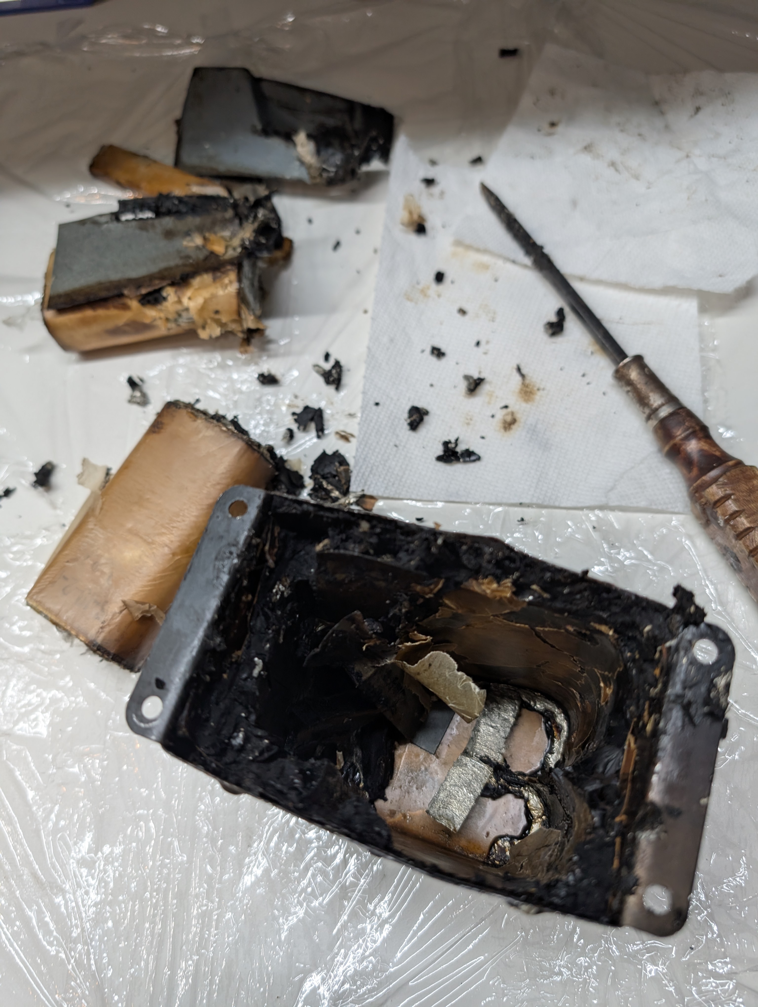
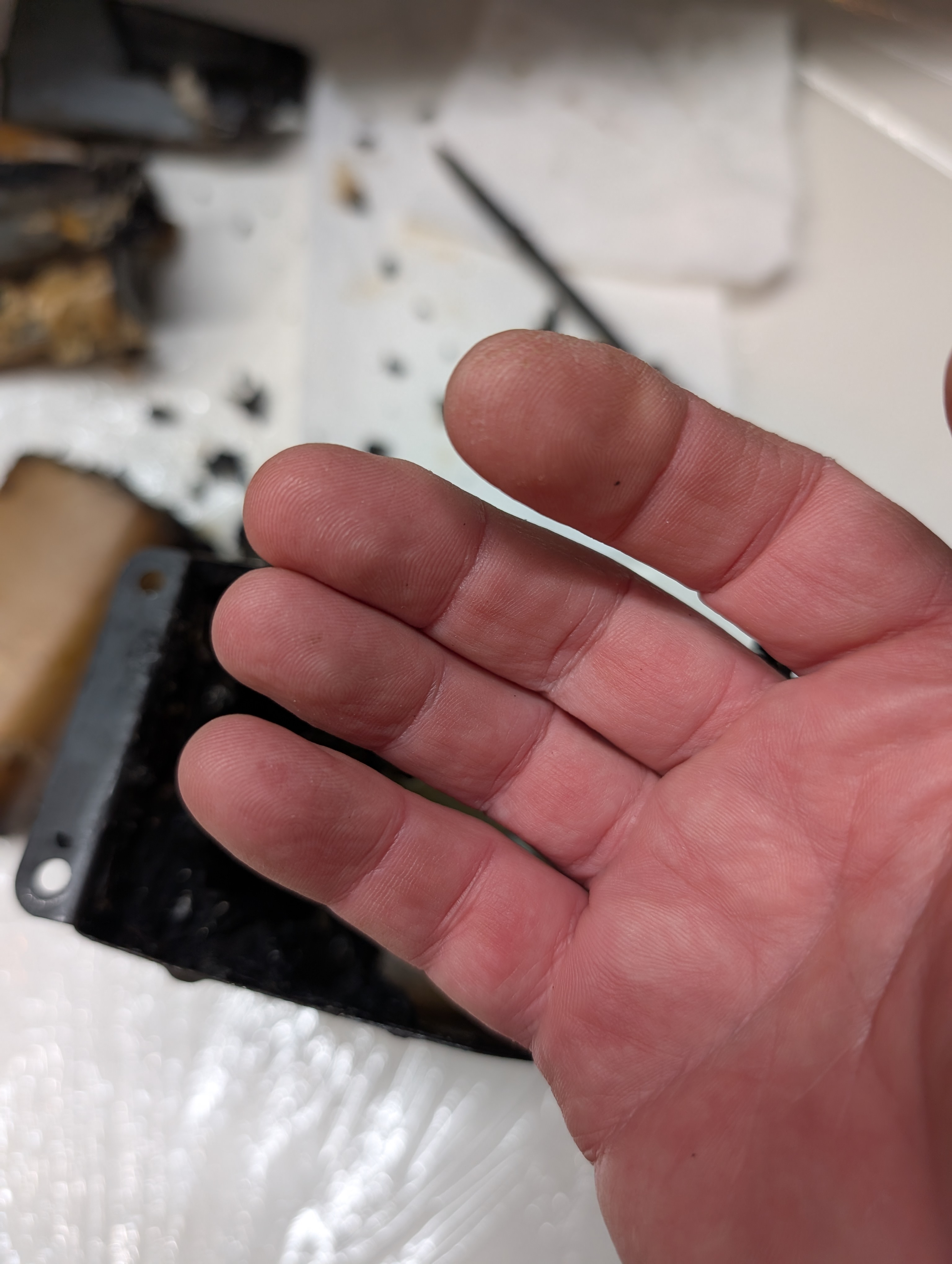
And I did not even dirtied my habds much!
Eventually, after having used heatgun to loosen the paper that was stuck to the can, and cleaned with mineral spirits, this is how it looks now.
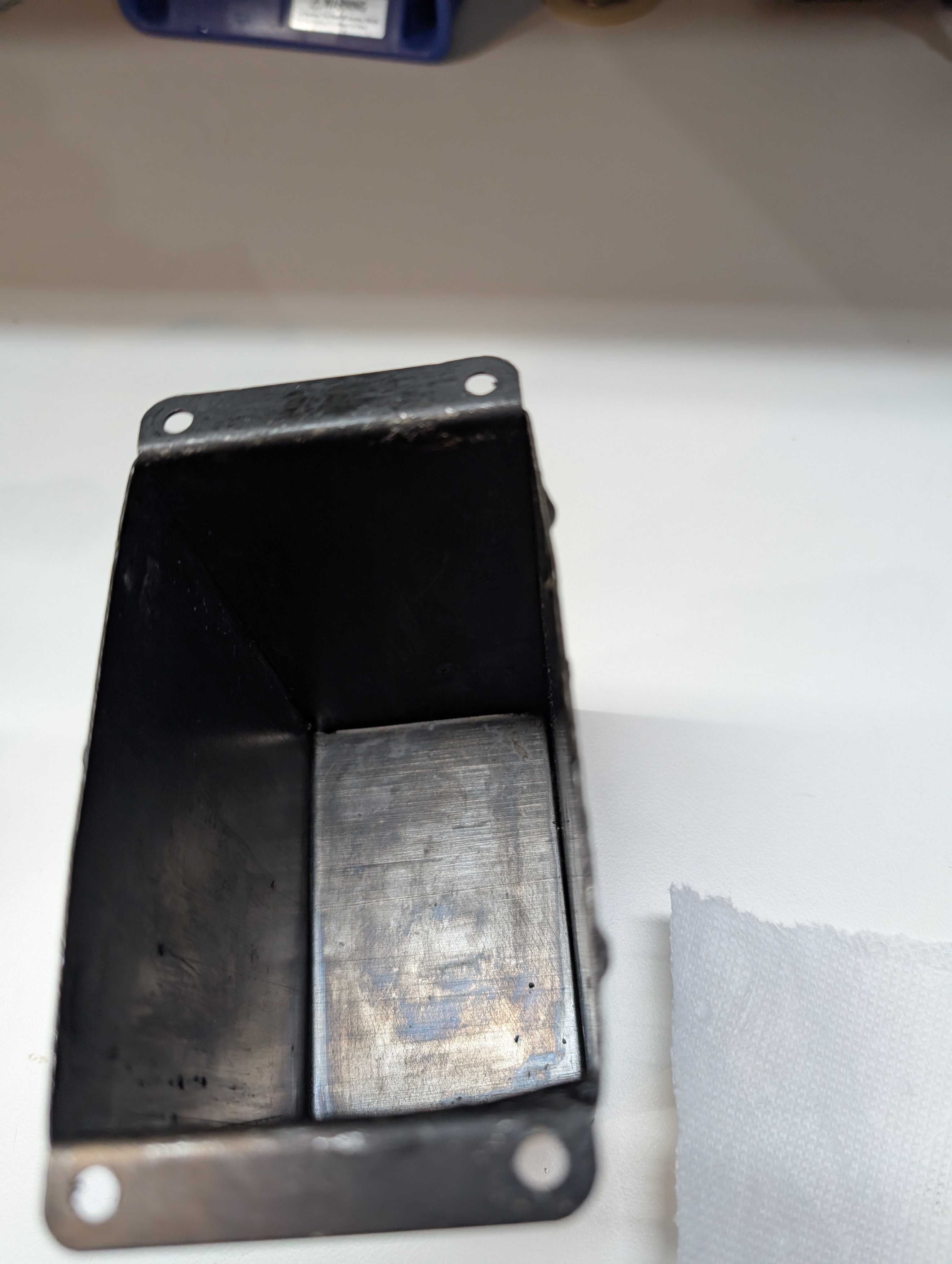
Tomorrow hopefully I will replace it (there is no need in paper lining) and attempt alignment.
And, after I am done with this radio, I might, using the experience, take on that 86 can that has been sitting on a shelf for a few years now.
People who do not drink, do not smoke, do not eat red meat will one day feel really stupid lying there and dying from nothing.
Posts: 16,559
Threads: 573
Joined: Oct 2011
City: Jackson
State, Province, Country: NJ
Have just aligned it. Surprisingly, it was not that much off at all. Barely.
Aligning TRF sets is pure pleasue, as there is no IF. Just 4 trimmer, all at the same 1300 kHz.
Done, the bottom chassis shield is put back.
Now the last thing I need to obtain is the speaker. I successfully used a 20 speaker for checks and alignment, but would prefer to have a G type. The eBay sellers want some exorbitant numbers. I will try mu luck in Kutztown this May.
If or when I get it, I will probably post the last video, to show the set receiving with the speaker in the cabinet, but for now this is it.
People who do not drink, do not smoke, do not eat red meat will one day feel really stupid lying there and dying from nothing.
Users browsing this thread: 1 Guest(s)
|
|
Recent Posts
|
|
1949 Motorola 5A9M
|
| Nice job on the battery, Bob. Can the box be opened to replace the 9 volters?RodB — 11:32 AM |
|
Philco 46-1209 strange behavior
|
| Thank you for the detailed response MrFixr.
To clarify, the hum starts when the tubes are fully warmed up, and goes a...sq65 — 09:15 AM |
|
Philco 46-1209 strange behavior
|
| MrFixr
The chassis, if there is no ground pin in the AC plug, due to the Y-caps from L/N to the chassis, is at 60VAC re...morzh — 08:47 AM |
|
schematics
|
| thanks I'll try the polar caps seperatelymseno — 07:38 AM |
|
Philco 46-1209 strange behavior
|
| Hi SQ55,
A strange issue indeed! Just so I have you straight, on a dim bulb you get normal operation after the set warm...MrFixr55 — 12:44 AM |
|
schematics
|
| I think mseno is talking about cap# 27 which is a multisection but in a paper tube. In cases like that I've usually be ...klondike98 — 11:25 PM |
|
schematics
|
|
Ohrenet :roll:
For their price I would chase a fly in a field. :twisted:Vlad95 — 11:21 PM |
|
1949 Motorola 5A9M
|
| A bit more work on the Motorola. I got the repro battery together right up until I realized the snap clips on the top o...klondike98 — 10:45 PM |
|
schematics
|
| Often restuffed.
If a twistlock, Hayseed Hamfest makes modern replacements.
morzh — 09:18 PM |
|
schematics
|
| Looking for a multi-sectional 8+16 mfd cap. Can't find any suppliers that carry it.mseno — 08:45 PM |
|
Who's Online
|
| There are currently no members online. |

|
 
|


![[-] [-]](https://philcoradio.com/phorum/images/bootbb/collapse.png)


