Posts: 1,391
Threads: 46
Joined: Nov 2017
City: Menlo Park
State, Province, Country: CA
I managed a bit more detective work on the radio today. Sometimes, it's helpful to have too many radios, and this was one of those times. I used a neat little communications receiver I own as an IF sniffer, just using a piece of insulated wire as a capacitive probe, with no risk of zapping it's delicate (solid state) front end.
The signal generator, set to 455kHz was loose coupled up to the Zenith, and the radio also tuned to 455 kHz. With this setup, I could listen in to each IF stage by setting the probe near the output of each IF transformer. The Zenith was allowed to warm up, at which point the fault started to make itself heard while receiving AM. I turned down the Zenith, turned on the generator, and listened on the probe radio. First and second IF stages seemed to be producing a clean signal, but the third stage was noisy. Switching the Zenith to a broadcast station I could confirm that the same noise heard at the third IF was also present on the Zenith's audio.
I'll think about whether there's any other possible source for the noise (check resistors etc.,) before tearing into the IF can, but - if you'll pardon the pun - I'm getting warmer 
Ed
I don't hold with furniture that talks.
Posts: 1,881
Threads: 120
Joined: May 2008
City: Omak
State, Province, Country: WA
Hello Ed,
yes , I have had noise disc capacitors and resistors plus even Mica capacitors .
I was restoring a RCA and after recapping the set there was a noise like that but it ended up to be a mica capacitor in the audio circuit set has worked flawlessly ever since.
Sincerely Richard
Posts: 1,391
Threads: 46
Joined: Nov 2017
City: Menlo Park
State, Province, Country: CA
Looking forward to some more work on this today. First off, to isolate the source of noise once and for all. I have a cunning plan to (temporarily) isolate the last IF stage and take the voltage off the suspect transformer. I could then inject modulated 455kHz through the transformerpirimary which should be detected without noise in this configuration, unless the source is another component.
Ed
I don't hold with furniture that talks.
Posts: 1,391
Threads: 46
Joined: Nov 2017
City: Menlo Park
State, Province, Country: CA
Well, the plan worked.
I unsoldered the wires to the primary of the third 455kHz IF transformer. A small toroid was made up as a 1:1 rf isolating transformer so that I could feed 455kHz from my generator, and apply HT to the IF primary without damaging the generator. This way guaranteed the test focused on the specific IFT. HT for the 3rd IF tube was also disconnected.
With just the generator connected, the modulated 455kHz signal came through clear and undistorted. Connecting 95V from the IF tube HT rail immediately brought on the familiar crashes and crackles which plague AM reception.
With that test concluded, it seems we "have our man", and I'm now about to descend into the dark underworld of IF can repairs...
I don't hold with furniture that talks.
Posts: 1,391
Threads: 46
Joined: Nov 2017
City: Menlo Park
State, Province, Country: CA
Well that was an adventure, and a successful one.
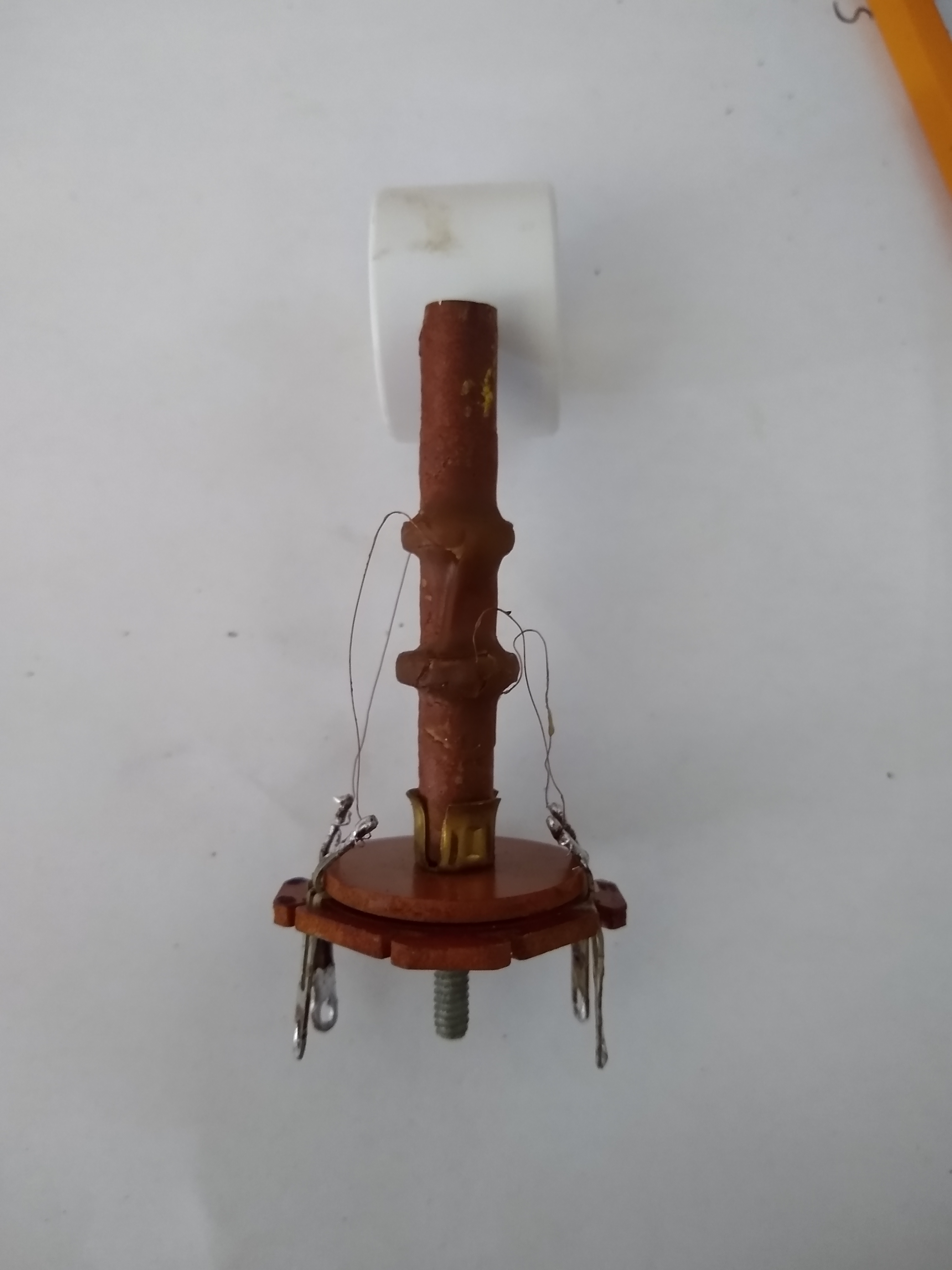
I removed the transformer, and took off the screening can:
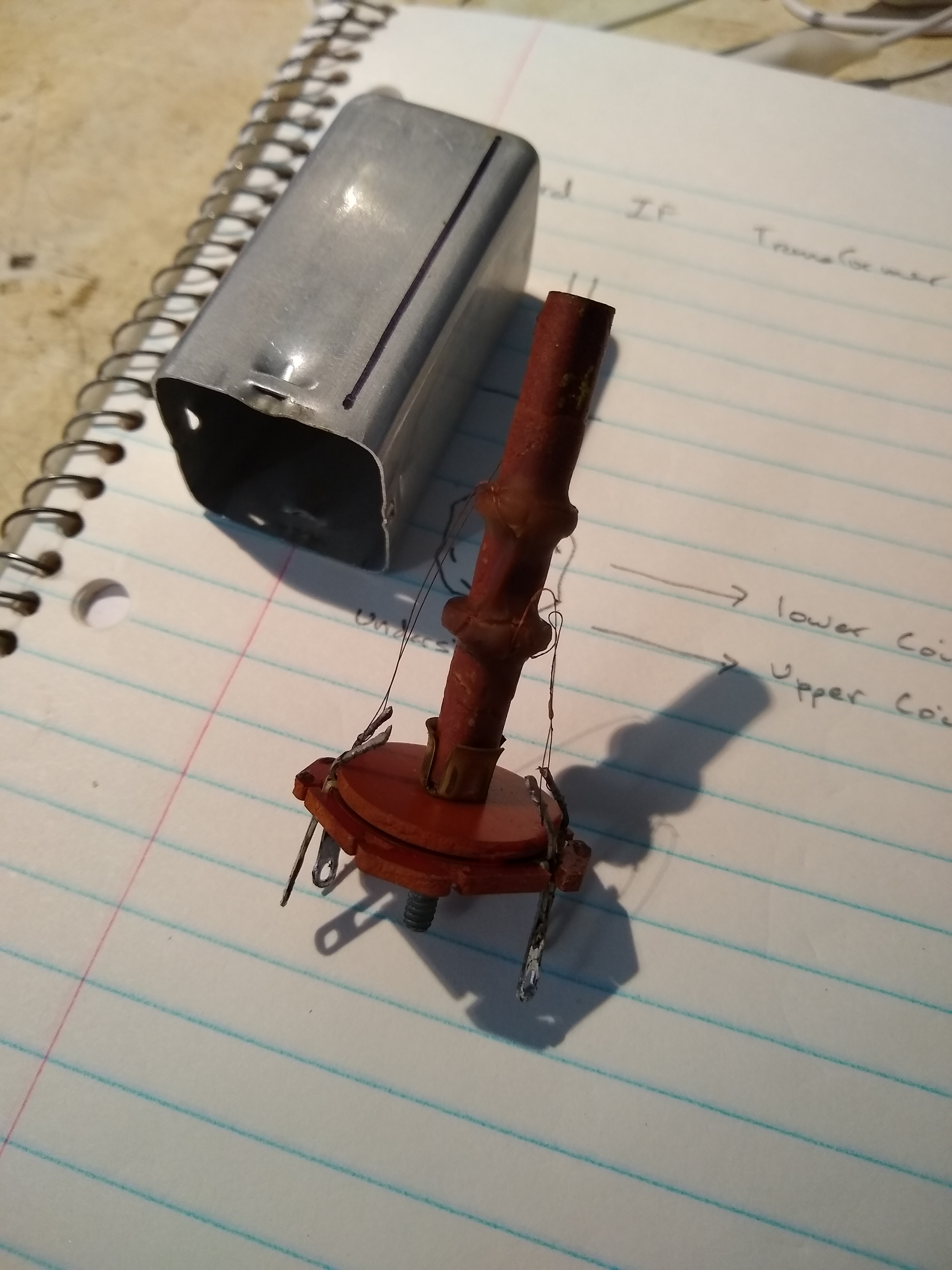
After desoldering the wires (noting all positions) removing the nut at the base released the coils, a top disc of phenolic, the mica disc, and its contacts:
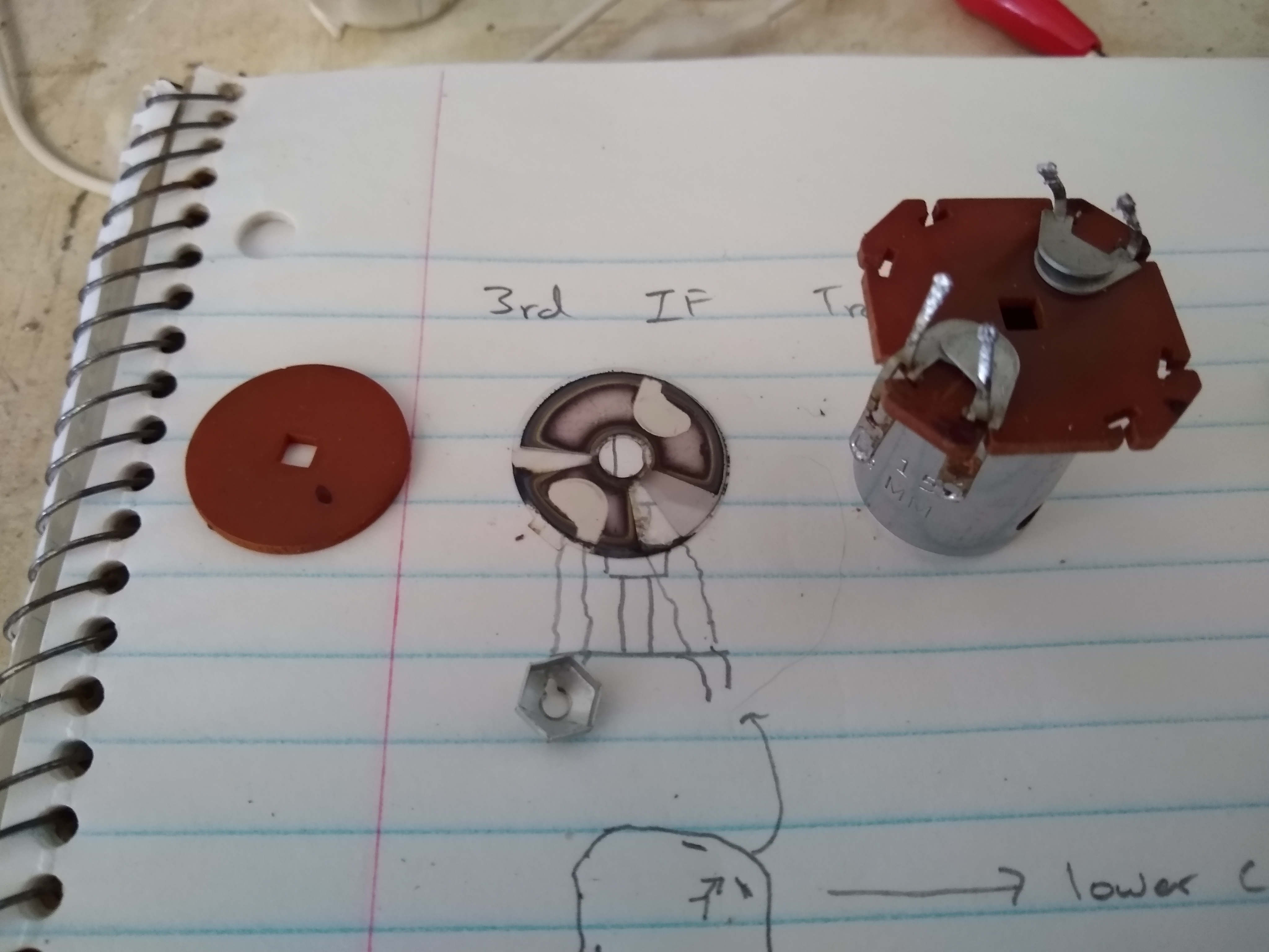
I found on line a description of using a pencil eraser to clean the mica. This one had clear tracking between the transformer primary and secondary tuning caps.
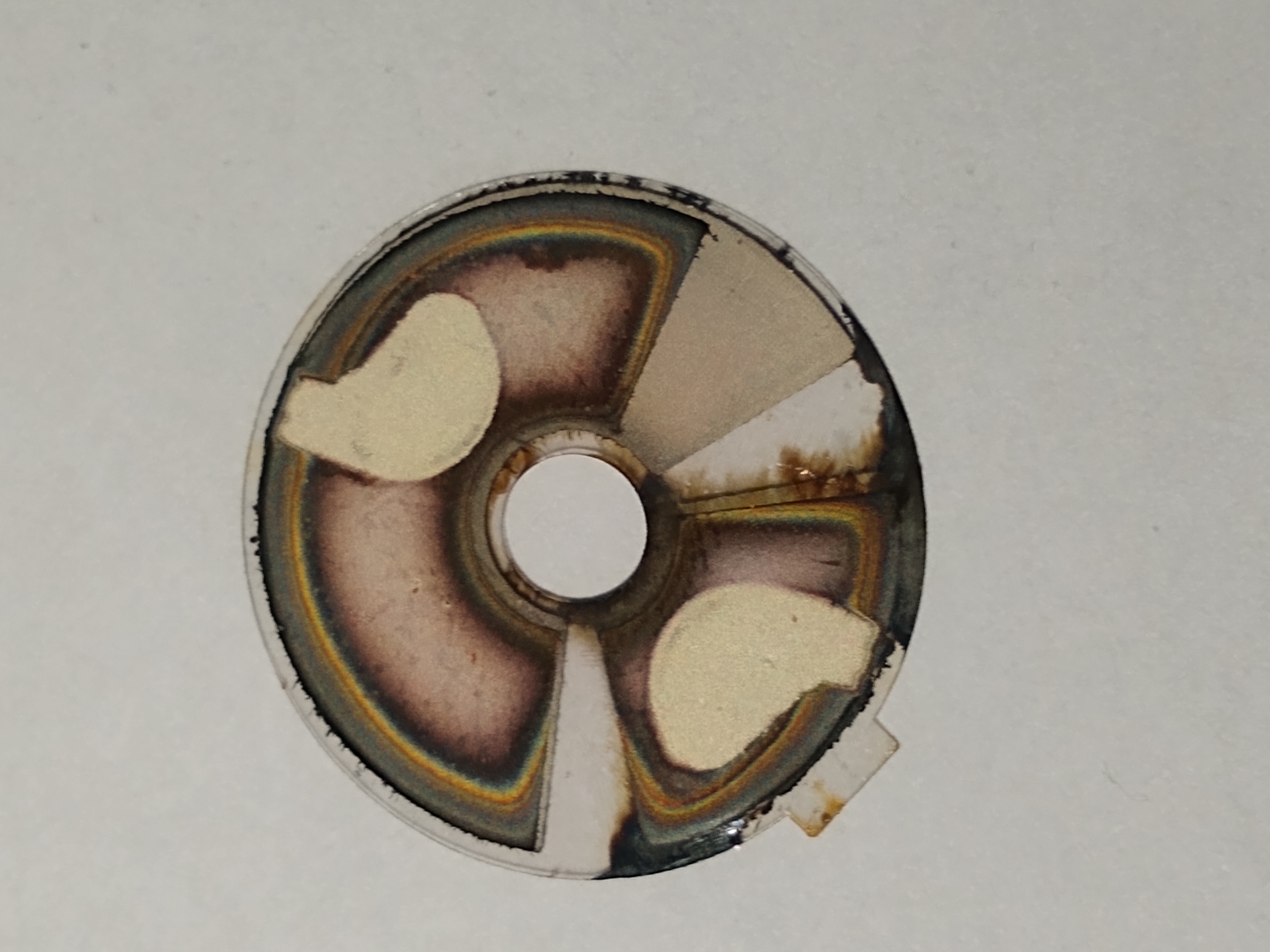
After cleaning, and managing not to break the mica, it looked like this:
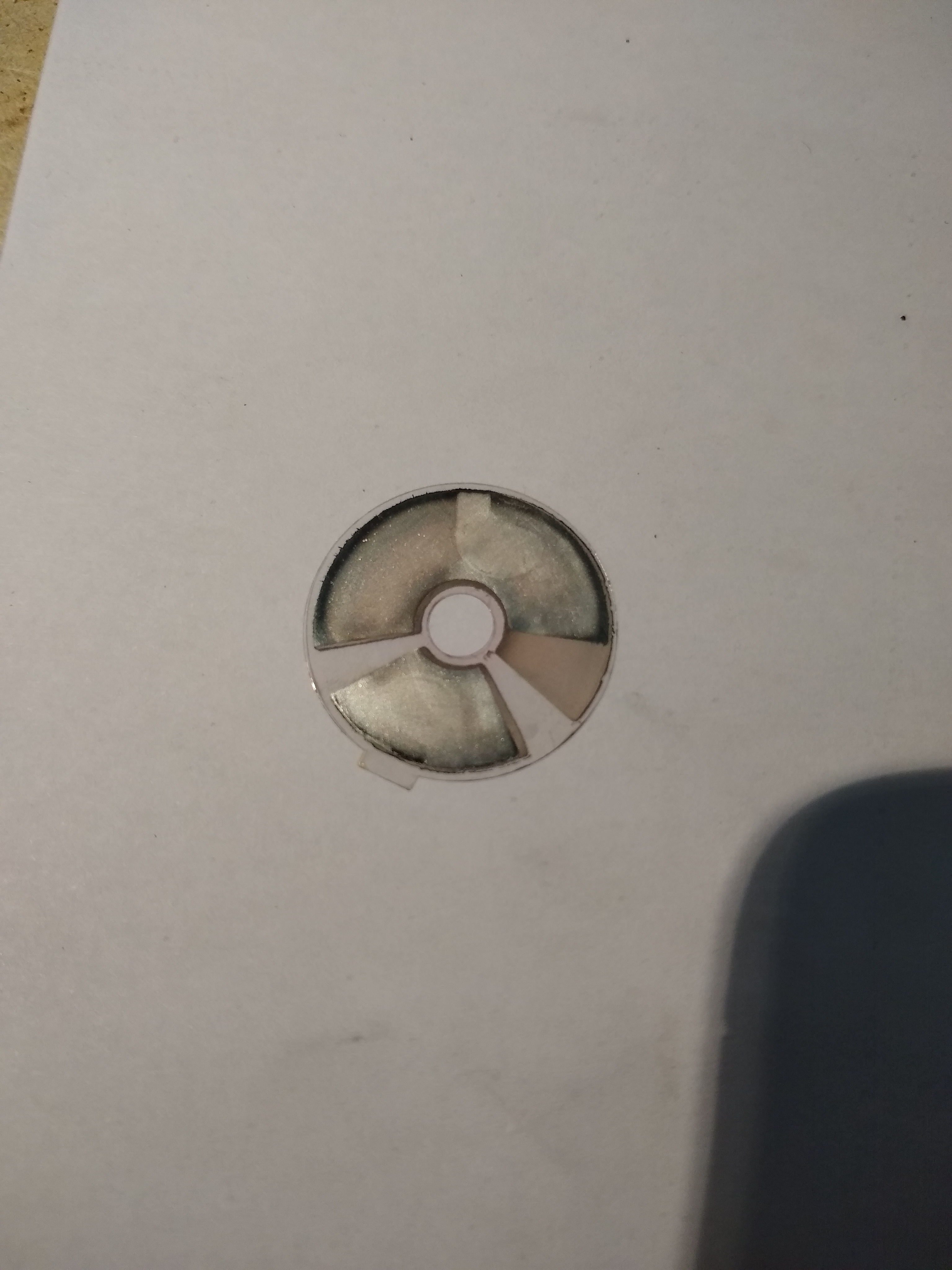
Wires reattached, and ready to go back on to the chassis:
I crossed my fingers and applied power. AM came up nicely, and stayed that way. No sign of the horrendous crashing noises, even after extended warm-up. Not so FM! Reception has started to go downhill, and with much the same fluttery interference. Part of this was the band-switch - I found a hidden section lurking inside a screening can near the tuner. Cleaning this improved things a little, but FM was still distorted, flickery and a mess. Using my "other radio" trick to probe along the IF chain, I injected a clean carrier and listened on 10.7 MHz. IF1, 2 and 3 were all clean, but at the discriminator, I got the same noise pattern from the probe radio and the Zenith's speaker. Looking at the schematic, there are caps inside the discriminator can. I'll do the same test and treatment on this part.
Fun day!
I don't hold with furniture that talks.
Posts: 1,391
Threads: 46
Joined: Nov 2017
City: Menlo Park
State, Province, Country: CA
Make that 2 cans fixed. Extracting the discriminator transformer was fiddly, as it's in the corner of the chassis, and there is a tag strip in the way. Then there are several components that have been looped through the tags, and the leads pass on to other tags on the chassis, and tube sockets.
The same clean-up procedure was carried out, along with adding a little silver paint to restore some areas of silvering that were damaged or missing, and hopefully get back to the target capacitances.
Anyway, FM now works much much better, no flutter and crackle or unsteady volume, and I've not even checked FM alignment yet.
Quite the unexpected adventure, but it was definitely SMD in both cases, and if you don't mind the delicate work, these type transformers can be cured. (at least for another 70 years LOL).
I don't hold with furniture that talks.
Posts: 1,391
Threads: 46
Joined: Nov 2017
City: Menlo Park
State, Province, Country: CA
I changed out the internal mains wiring, and reconfigured it to switch the live line - an assumption based on the polarised plug and new cable I fitted to the back. A good cheap way to do this was to buy a brown 6ft 2 wire lighting extension cord. It even looks the part!
Then it was on to FM IF alignment, once I found the test points A, B and C on the correct schematic, and their location in the chassis. Then it all made sense. I've only done a couple of FM sets, so still a bit of a novice with these methods. Anyway, the result is much improved reception and nice clean audio. These little sets are absolute belters. Despite barely 130V HT, and a small pentode single ended output circuit, the big speaker is efficient and has a great response - And this is still listening on the bench with it out of the cabinet. I'm very impressed.
I don't hold with furniture that talks.
Posts: 1,881
Threads: 120
Joined: May 2008
City: Omak
State, Province, Country: WA
Hello Ed,
nice Save on the two IF cans hopefully that will hold up !
Sincerely Richard
Posts: 1,262
Threads: 11
Joined: Jul 2020
City: Greenlawn
State, Province, Country: NY
Hi Ed,
Congrats!! It is precisely the 130V V and 8" speaker that makes the set sound good. Sets with a tube half wave rectifier only put out between 90 and 110V to the output tube plate. Between 120V from the utility and replacing the selenium rectifier with a silicon diode, you can squeeze much more out of it.
Philco made several "table" sets in the late 1940s and early 1950s (actual tables) with AM - Phono chassis. These sets used an 8" speaker and a full wave voltage doubler rectifier. The 49-1606 AM FM Phono Console puts 195V on a 50C6 Output tube (Beam power), yielding 5W. This is about as much as you can get out of a 35L6 or similar AA5 Output tube.
"Do Justly, love Mercy and walk humbly with your God"- Micah 6:8
"Let us begin to do good"- St. Francis
Best Regards,
MrFixr55
Posts: 1,264
Threads: 32
Joined: Jan 2014
City: Wellborn Florida
Nice save like the way you cleaned the mica. Years ago made a replacement mice globe for a lamp seeing your repair makes my globe look like a kids project. Well Done David
Posts: 1,391
Threads: 46
Joined: Nov 2017
City: Menlo Park
State, Province, Country: CA
The mica save was inspired/encouraged by this gem I found:
https://www.boatanchors1.com/zenithifcan.html
I'd wondered if it could be done, and for this style of transformer, it is possible if you are careful and have the nerve for it!
My minor dilemma now is that there are 5 more IF cans. Although there are no signs of trouble, the OCD side of me says they should all be checked. The leave well-alone side of me fears causing a problem...
Meanwhile, I found a suitable replacement for the 4 section electrolytic which should arrive in a few days. A slightly expensive approach, but as this radio is going back out "into the wild" it is the best option. I found one with 200 V ratings (50V on the fourth section), so a nice extra safety margin where it is needed. The diameter is the same, and although it's about 0.5" taller, this will not present a problem
I don't hold with furniture that talks.
Posts: 1,199
Threads: 49
Joined: Oct 2017
City: Allendale, MI
I also have a 7H820. Nice little radio and I use it often. Obviously the old FM band is quite useless! It's only use for me is to generate white noise to fall asleep to.
Posts: 1,148
Threads: 47
Joined: Feb 2015
City: Roseville, MN
I suppose it's too much work to modify the oscillator for the FM tuning 88-108.
Posts: 1,391
Threads: 46
Joined: Nov 2017
City: Menlo Park
State, Province, Country: CA
Interesting thought, Rod. Our 1947 Zenith console has both FM bands, so presumably it could be done with appropriate changes to the caps in the oscillator circuit - the permeability tuned coils are used for FM both bands, and don't seem to have special taps or sections.
I don't hold with furniture that talks.
Posts: 1,391
Threads: 46
Joined: Nov 2017
City: Menlo Park
State, Province, Country: CA
The PSU filter cap arrived today (thank you USPS!) so I will work on that later.
Meanwhile, I have the dial, speaker grille and badges cleaned up and refitted. It is starting to look like a radio again.
One thing I need is something to replace the heat insulation that was inside the top of the case, where the OP tube would deliver most heat. Any thoughts on what to use here?
I don't hold with furniture that talks.
Users browsing this thread: 2 Guest(s)
|
|
Recent Posts
|
|
Philco 50-925 antenna connections
|
| Finally, got the antenna fixed (repaired some broken wires) and have the radio playing. I've got four different schemat...keith49vj3 — 09:38 PM |
|
1949 Motorola 5A9M
|
| Bob, Nice radio. I’ve not seen one before. Keep us updated!Joe Rossi — 07:56 PM |
|
Phioco 90 Power Transformer Wire Colors
|
| Thanks for adding that information.klondike98 — 06:09 PM |
|
Phioco 90 Power Transformer Wire Colors
|
| Although I have used this site as a resource for a number of years this is my first post. I am restoring a Model 90 si...vincer — 05:02 PM |
|
My collection presentation
|
| There is a complete instruction how to solve your problem. One piece of advice - be careful with the low-voltage capacit...Vlad95 — 09:32 AM |
|
My collection presentation
|
| Vlad;
I thought your brown RCA portable looked familiar, I have one that is very similar, the RCA-Victor model BX-55....Arran — 02:31 AM |
|
Value of capacitor
|
| OP is "original poster"klondike98 — 11:05 PM |
|
Value of capacitor
|
| What is an OP? Looks like the “OP” mistakenly typed electrolytic. Lets forgive him.Joe Rossi — 06:31 PM |
|
Another amp build - here I go again!
|
| How many amps a man can have?
I say, as many as the space can hold.morzh — 10:01 AM |
|
Value of capacitor
|
| >>>It currently has an .005 1000 volt electrolytic that is at least 40 years old. That needs to go.
There i...morzh — 10:00 AM |
|
Who's Online
|
There are currently 484 online users. [Complete List]
» 1 Member(s) | 483 Guest(s)
|
|
|

|
 
|


![[-] [-]](https://philcoradio.com/phorum/images/bootbb/collapse.png)


