2 hours ago
Hey all! Well, I guess that with what I learned from my last build, it's time to move up the ladder another rung and take a shot at a more powerful amp build. With mowing (and rain) season upon us, this will be a rather long build. Hopefully finished by fall. I'm hoping for around 50w out of this one using some of the common and good performing Dynaco circuit and readily available off the shelf current production parts that anyone following this thread can duplicate. I'm using a prepunched stainless chassis from over seas (eBay) which is attractive, inexpensive and comes with almost all the hardware you would need. It looks different than my previous builds and will be lightly modded in staying with a more traditional old school design. While sticking to a very common schemo, I am also looking at the Williamson and Mullard design, but with my limited socket holes (octal), I may try the Dyna circuit using a triode/pentode driver, and a par of 6L6GC outputs. This, as before, will be my design (with the assistance of others) using fixed bias and the KISS theory. I figure if Dynaco can get 60w out of this simple circuit, I should be able to get 50w using similar design, transformers, voltages and currents.
As of this writing, I have the layout of the major components in place and it will be built similar to my previous attempt. I'm using a beefy Hammond PT with enough juice to put my voltages in the mid/high 400v range with 200+ma force. Enough filament for 20 tubes and 5 rectifiers (alright, maybe one current hungry 5R4 and a handful of sound bottles) and a nice affordable 50w UL, 5k output tranny. Yeah, it's from overseas (also eBay), but on some initial live power tests sounds very "alive". Trying to keep costs down and quality up. Most of the parts virtually bolted right in place with a half dozen new holes drilled to make it right. So far, very simple and straightforward. Sure, nitpickers will see some errors, but for a prefab, this is very affordable and works nicely with my choice of iron. Ok, so just how am I gonna use triode/pentode drive in an octal hole? Well, a nice little 9pin to octal adapter! Oh no, not one of those hobcob socket adapters that sticks up 2" with a variety of different sockets hanging out the top! Nope noooo, this is a real adapter that allows me to screw a 9pin socket into an octal hole! And, I think it looks "factory"!
Now, this is NOT a kit, nor is it a sacrificed/modded kit. This is a fresh, ground up build and has been a goal of mine since a youth. And yeah, it'll be a pair of mono blocks.
Anyway, below are a few pics of the proposed build to date, and will be a rainy day project through the summer. Yes, I have powered things up and "hum tested" to check the placement of my transformers. Even a 1/16th inch movement makes a difference (PT powered up and headphones connected to speaker wires).

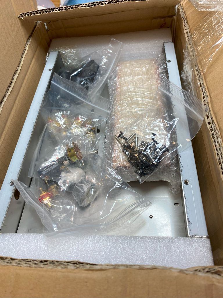
Chassis kit. This came with bottom, wood sides, speaker posts, power cord & plug, line control, feet, knob, screws, input jacks - just about everything exc tube sockets and components. It's a little narrower than the kits, but deeper and thicker.

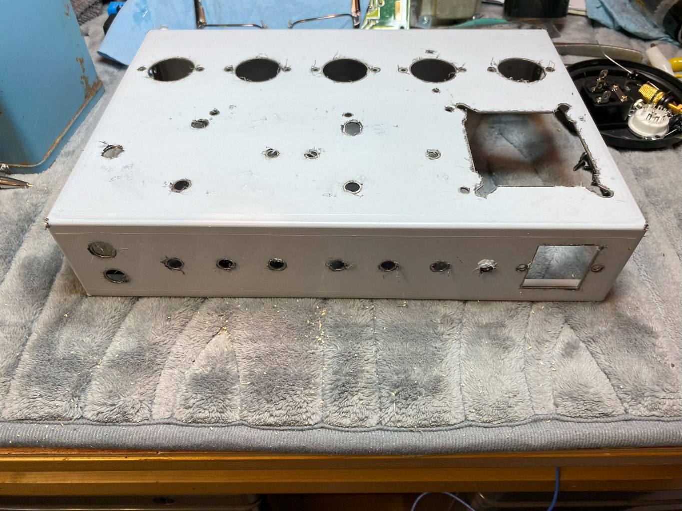
Holes drilled

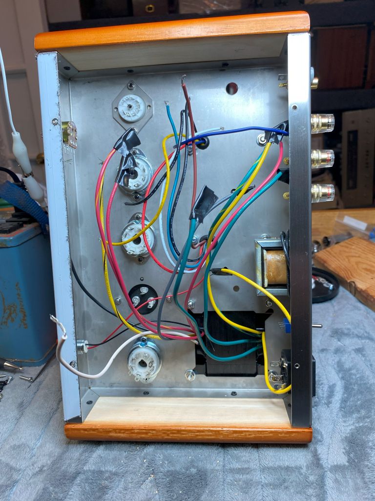
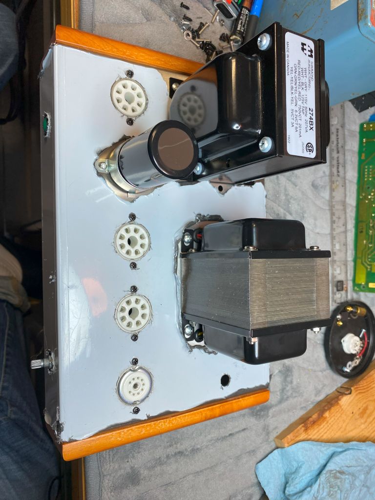
My choke screwed perfectly to to the inside rear of the chassis, and the power trans covers the recess hole for the laydown trans designed for. Had to trill a couple mounting screw holes. The output tranny lined up almost perfect, however I did also have to drill a couple mounting screw holes and enlarge a hole to allow the primary wires to pass through the chassis. The secondary used the existing hole (and grommets). You can also see my socket adapter which sandwiches the 9pin bracket between the chassis and adapter and allows you to turn the socket any direction needed. It's solid and doesn't move at all. No mods to the chassis so if I decide to use an octal tube, it's a simple drop out and replace with octal socket. I also mounted the filter cap on top of the chassis, but found that if I need to use the hole for another socket, it can be mounted underneath near the PT using a strap bracket. I can also go SS on the rectifier and free up a hole, but as of now, I'm planning on a bulb. I also drilled a 1/4" hole on the rear near the power plug for a mini switch and enlarged an existing hole on top near the driver tube for a bias control. It can also be enlarged if I want/need to add an additional 7 pin driver tube if needed. Control can be moved somewhere else or put underneath the chassis.

The Mk3 diagram - which is identical to the Mk4 exc for the output tubes, choke, and couple very minor component value differences. I'll likely use a variant between the two and slightly different bias supply since my PT doesn't have a bias winding. I'll likely use a 6U8a or 6GH8a driver tube, but if it doesn't perform well, the 6AN8a tubes are readily available, just a little more costly, but still reasonable. I'll wire it in such as way as 6CA7 (EL34) can be used with a minor bias adjustment (pin 1 grounded).
As of this writing, I have the layout of the major components in place and it will be built similar to my previous attempt. I'm using a beefy Hammond PT with enough juice to put my voltages in the mid/high 400v range with 200+ma force. Enough filament for 20 tubes and 5 rectifiers (alright, maybe one current hungry 5R4 and a handful of sound bottles) and a nice affordable 50w UL, 5k output tranny. Yeah, it's from overseas (also eBay), but on some initial live power tests sounds very "alive". Trying to keep costs down and quality up. Most of the parts virtually bolted right in place with a half dozen new holes drilled to make it right. So far, very simple and straightforward. Sure, nitpickers will see some errors, but for a prefab, this is very affordable and works nicely with my choice of iron. Ok, so just how am I gonna use triode/pentode drive in an octal hole? Well, a nice little 9pin to octal adapter! Oh no, not one of those hobcob socket adapters that sticks up 2" with a variety of different sockets hanging out the top! Nope noooo, this is a real adapter that allows me to screw a 9pin socket into an octal hole! And, I think it looks "factory"!
Now, this is NOT a kit, nor is it a sacrificed/modded kit. This is a fresh, ground up build and has been a goal of mine since a youth. And yeah, it'll be a pair of mono blocks.
Anyway, below are a few pics of the proposed build to date, and will be a rainy day project through the summer. Yes, I have powered things up and "hum tested" to check the placement of my transformers. Even a 1/16th inch movement makes a difference (PT powered up and headphones connected to speaker wires).
Chassis kit. This came with bottom, wood sides, speaker posts, power cord & plug, line control, feet, knob, screws, input jacks - just about everything exc tube sockets and components. It's a little narrower than the kits, but deeper and thicker.
Holes drilled
My choke screwed perfectly to to the inside rear of the chassis, and the power trans covers the recess hole for the laydown trans designed for. Had to trill a couple mounting screw holes. The output tranny lined up almost perfect, however I did also have to drill a couple mounting screw holes and enlarge a hole to allow the primary wires to pass through the chassis. The secondary used the existing hole (and grommets). You can also see my socket adapter which sandwiches the 9pin bracket between the chassis and adapter and allows you to turn the socket any direction needed. It's solid and doesn't move at all. No mods to the chassis so if I decide to use an octal tube, it's a simple drop out and replace with octal socket. I also mounted the filter cap on top of the chassis, but found that if I need to use the hole for another socket, it can be mounted underneath near the PT using a strap bracket. I can also go SS on the rectifier and free up a hole, but as of now, I'm planning on a bulb. I also drilled a 1/4" hole on the rear near the power plug for a mini switch and enlarged an existing hole on top near the driver tube for a bias control. It can also be enlarged if I want/need to add an additional 7 pin driver tube if needed. Control can be moved somewhere else or put underneath the chassis.
The Mk3 diagram - which is identical to the Mk4 exc for the output tubes, choke, and couple very minor component value differences. I'll likely use a variant between the two and slightly different bias supply since my PT doesn't have a bias winding. I'll likely use a 6U8a or 6GH8a driver tube, but if it doesn't perform well, the 6AN8a tubes are readily available, just a little more costly, but still reasonable. I'll wire it in such as way as 6CA7 (EL34) can be used with a minor bias adjustment (pin 1 grounded).
If I could find the place called "Somewhere", I could find "Anything"
Tim
Jesus cried out and said, "Whoever believes in me , believes not in me but in him who sent me" John 12:44


![[-] [-]](https://philcoradio.com/phorum/images/bootbb/collapse.png)


