Posts: 162
Threads: 37
Joined: Dec 2009
City: Johnston, IA
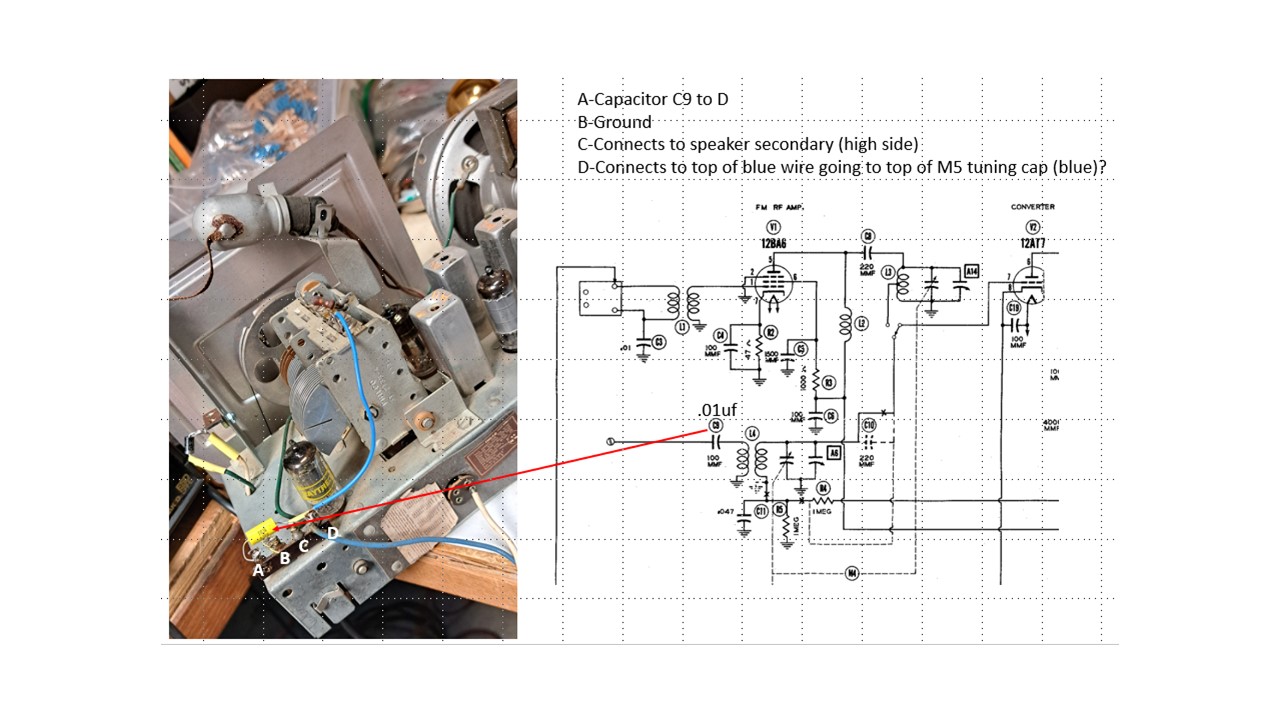
All, I picked up a Philco 50-925 for a couple of dollars so I could demo sweep alignments for folks in my radio club. This radio has not been worked on before with the exception of the 4 antenna wires in the cabinet and the blue wire going to the top of the tuning cap that had been cut. The cabinet loop antenna has four leads and none have continuity between them. These attach somewhere on the four post terminal strip shown in the photo below. There is a green wire on what I have labeled terminal C that connects to the high side of the audio transformer secondary. This is not shown in any of the available schematics but is visible on the SAMs photofact and other pictures I've found online. I haven't found any information on how the loop antenna connects to the radio. I did attach a long wire antenna to the terminal I've got marked "A" and can pick up a few AM stations. For those that have a subscription to radiomuseum the SAMS and Rider schematics can be found here
radiomuseum schematic. Antique Electronic supply also has the schematic posted here
schematic. Can anyone help me figure out these connections? What's with the high side of the audio transformer going to terminal C?
Help!
Keith


Posts: 162
Threads: 37
Joined: Dec 2009
City: Johnston, IA
I forgot to mention that the IF and audio stages for AM work and FM plays great. Really confused by the antenna set up.
Keith
Posts: 162
Threads: 37
Joined: Dec 2009
City: Johnston, IA
Shoot, just realized that the blue wire connecting to the top of the tuning cap can't go to terminal D since that's on the wrong side of L4 so this must go somewhere else.
Posts: 1,148
Threads: 47
Joined: Feb 2015
City: Roseville, MN
C is for an external speaker.
Posts: 162
Threads: 37
Joined: Dec 2009
City: Johnston, IA
Thanks Rod, That makes perfect sense. Is there a way to edit my post? It's a Philco 50-925 and not a Philco 50-295. Did Philco ever produce their own service info or did they farm it out to Riders and SAMS? Should there be continuity between the four antenna wires? There is a low resolution photo of the top of the radio chassis on the radiomuseum website. The photo appears to show two wires going to "A", on wire going to "B" and the forth going to the tube of the tuning condenser. But its not clear what attaches to D.
Getting closer.
Keith
Posts: 882
Threads: 51
Joined: Feb 2013
City: Shenandoah,
State, Province, Country: Pennsylvania
Hi Keith, here is the official Philco service info found in the Philco Library under service info……https://philcoradio.com/library/download/service%20info/yearbooks/1950/split/Part12-Philco%20Home%20Radio%20Yearbook%201950-final.pdf
Ron
Bendix 0626. RCA T64 Philco 20B
Philco 41-250. Philco49-500
GE 201. Philco 39-25
Motorola 61X13. Philco 46-42 Crosley 52TQ
Philco 37-116. Philco 70
AK 35 Philco 46-350
Philco 620B. Zenith Transoceanic B-600
Philco 60B. Majestic 50
Philco 52-944. AK 84
Posts: 2,177
Threads: 158
Joined: Jan 2013
City: Westland, MI
Hello Keith! I've updated your thread with the proper model number. Take care, - Gary
"Don't pity the dead, pity the living, above all, those living without love."
Professor Albus Dumbledore
Gary - Westland Michigan
Posts: 1,148
Threads: 47
Joined: Feb 2015
City: Roseville, MN
Most loop antenna setups are either one continuous loop with two connections or 2 loops with 4 connections. The latter can be considered an rf transformer with the primary winding capabile of attachment to an external antenna, the secondary to the rf amp tube. So, you should get continuity on one pair and continuity on the other. In addition the antenna is usually used for a path of the AVC connection to the grid of the rf amplifier. The link that Ron provided above has this clear example of your antenna.
SAMs and Riders came after the fact and I believe they worked with most manufacturers to get their info. At times there's no way they would be able to know all the makers of radios. Beitman Supreme Publications are another source though they don't have complete coverage of all models, as they publish *the most popular schematics". Their diagrams are usually very clear but limited to just the schematic and sometimes alignment data.
Posts: 162
Threads: 37
Joined: Dec 2009
City: Johnston, IA
Finally, got the antenna fixed (repaired some broken wires) and have the radio playing. I've got four different schematics all with differences in the antenna circuitry. Mine must be from the first run.
Thanks everyone.
Keith
Posts: 1,882
Threads: 120
Joined: May 2008
City: Omak
State, Province, Country: WA
Hello Keith,
great news !!
Sincerely Richard


![[-] [-]](https://philcoradio.com/phorum/images/bootbb/collapse.png)


