Philco 90 - someone's been in here before!
Posts: 24
Threads: 8
Joined: Apr 2017
City: Weston, CT
I recently acquired a Philco 90 locally. This is the "mid" model with one 47. The cabinet is actually very nice and has a good original finish.
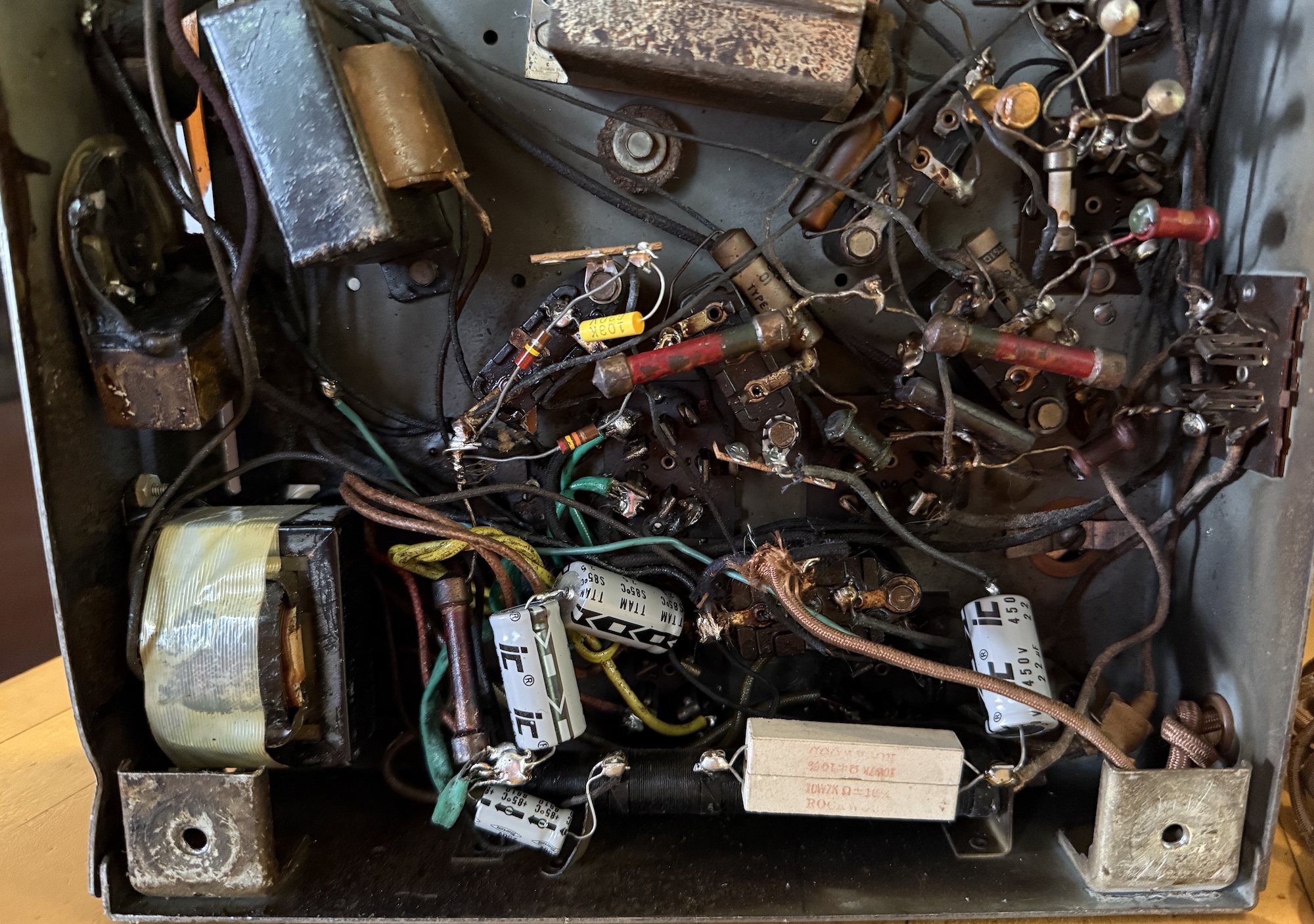
When I pulled the chassis out, I noticed that at some point in the past it had a catastrophic power transformer failure. Tar everywhere, and tar residue all over many components. Sometime possibly in the late 90's, a replacement Stancor transformer was installed along with a filament transformer for the output tube, the electrolytics were replaced, the 3.5k section of the bias resistor was bridged, and one capacitor and resistor was replaced. This is in addition to a number of bakelite blocks bypassed with paper caps many years ago. This was clearly a well-loved radio. I should be able to clean up most of the tar with a heat gun and lots of paper towels, and the new transformer plus filament transformer seem correct, at least.
I may be wrong, but I suspect this was the work of a local shop that opened in the 1940's and closed in the early 2000's. They specialized in tube electronics, but had a repair-only mentality.
Unfortunately I'm not sure I understand what they were doing with the electrolytics. The first filter is two 22uf 450v caps in series, negative to center tap, with a smaller modern 250v electrolytic cap connected from center tap to ground (positive to ground).
The second filter cap still has an ancient cap from the 50's connected, though it's taped together and the repairman may have not noticed it. An additional modern cap has been installed from the far side of the 3.5k section of the bias resistor (other side of the field coil), with the negative to ground.
Normally if I get a set that's been worked on in the recent past I'd power it up slowly to see where it's at. Since this seems so... wrong... I don't think I want to do that. Should I be putting this back to the schematic? Or did the last person know something I don't?
Posts: 5,652
Threads: 56
Joined: Sep 2008
City: Sandwick, BC, CA
Mid production model 90s are common enough that you should be able to find the original parts that are missing, if not a complete chassis that was less molested. I would have to review that schematic to see what you mean with the filter caps, but it wouldn't be the first time where someone confused the connections of the filter caps in a pre war radio. Typically they assume the filter caps are both grounded to chassis like they are in 90% of the radios built from the 1940s onward, but they can't really do this on power output tubes with directly heated cathodes, like #47s, #45s, etc. due to the way bias has to be obtained.
Regards
Arran
Posts: 24
Threads: 8
Joined: Apr 2017
City: Weston, CT
I decided to just jump in and go for it. I replaced all caps in the bakelite blocks, metal cans, and tone control. Found 2 open resistors (and a few others that read high that I'll eventually change). This was the power supply/audio section before:
And now:
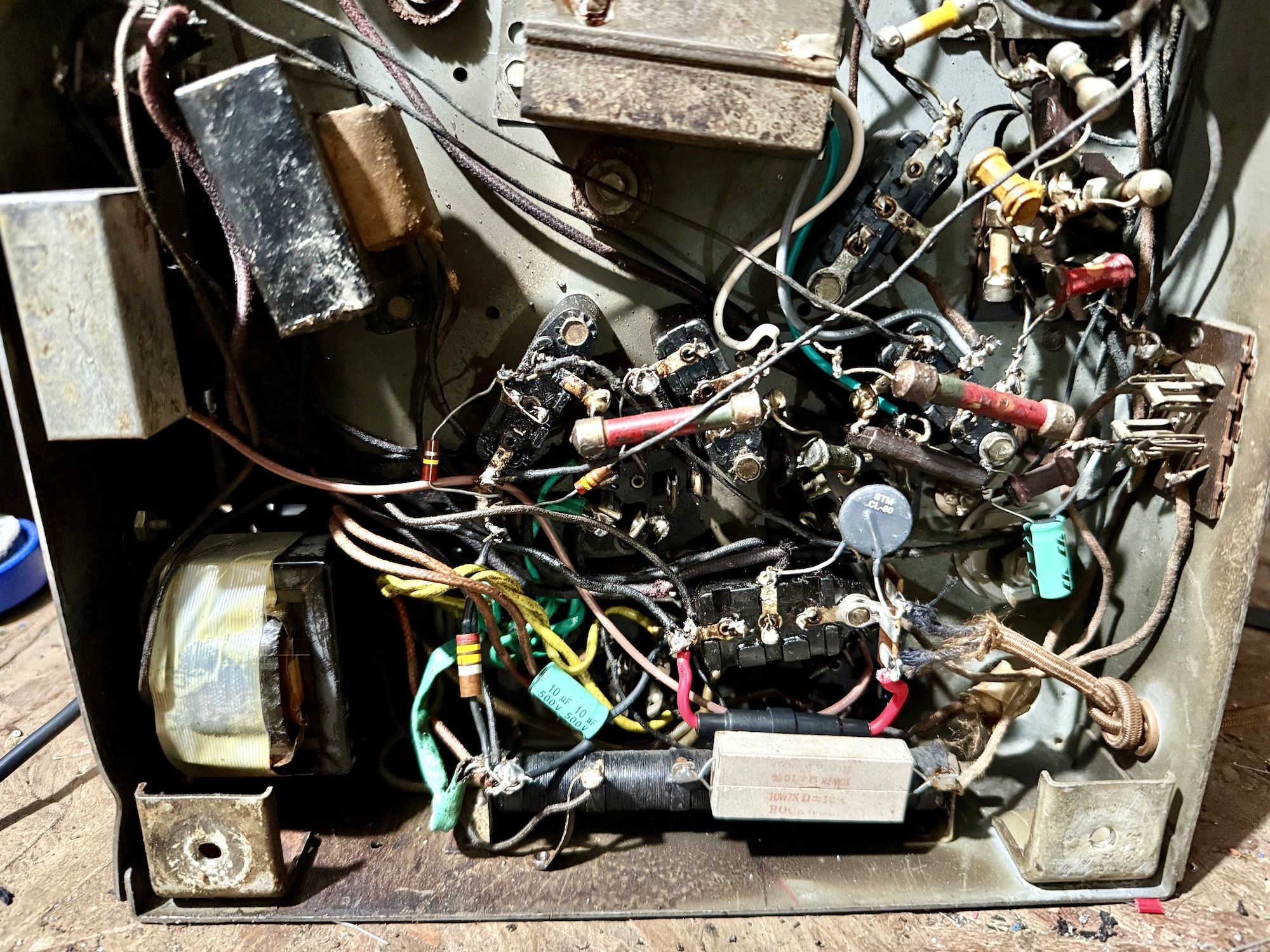
Wired new 10mf 500v electrolytics as per the schematic, added a fuse and a thermistor. Got most of the tar cleaned up with a heat gun, paper towels, and mineral spirits. It's a lot better on top, though underneath still has a fair bit of tar.
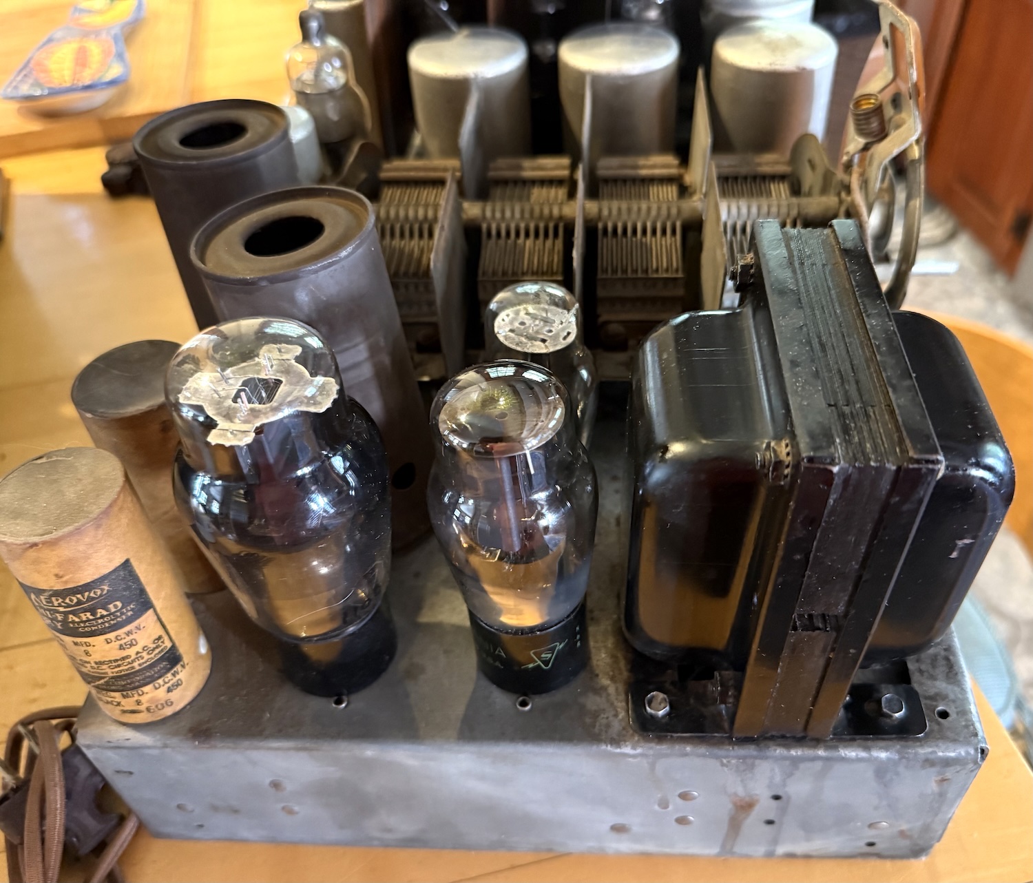
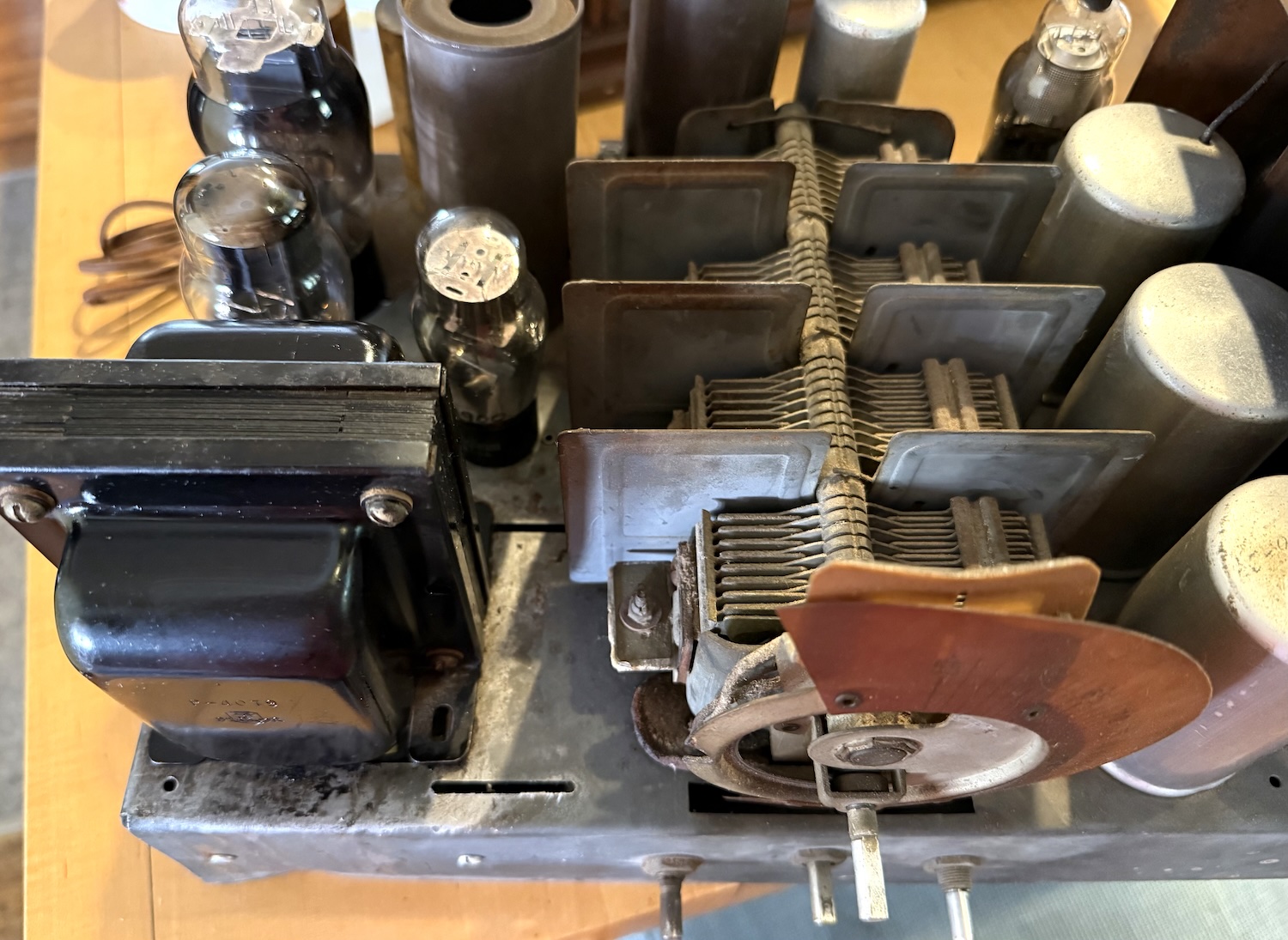
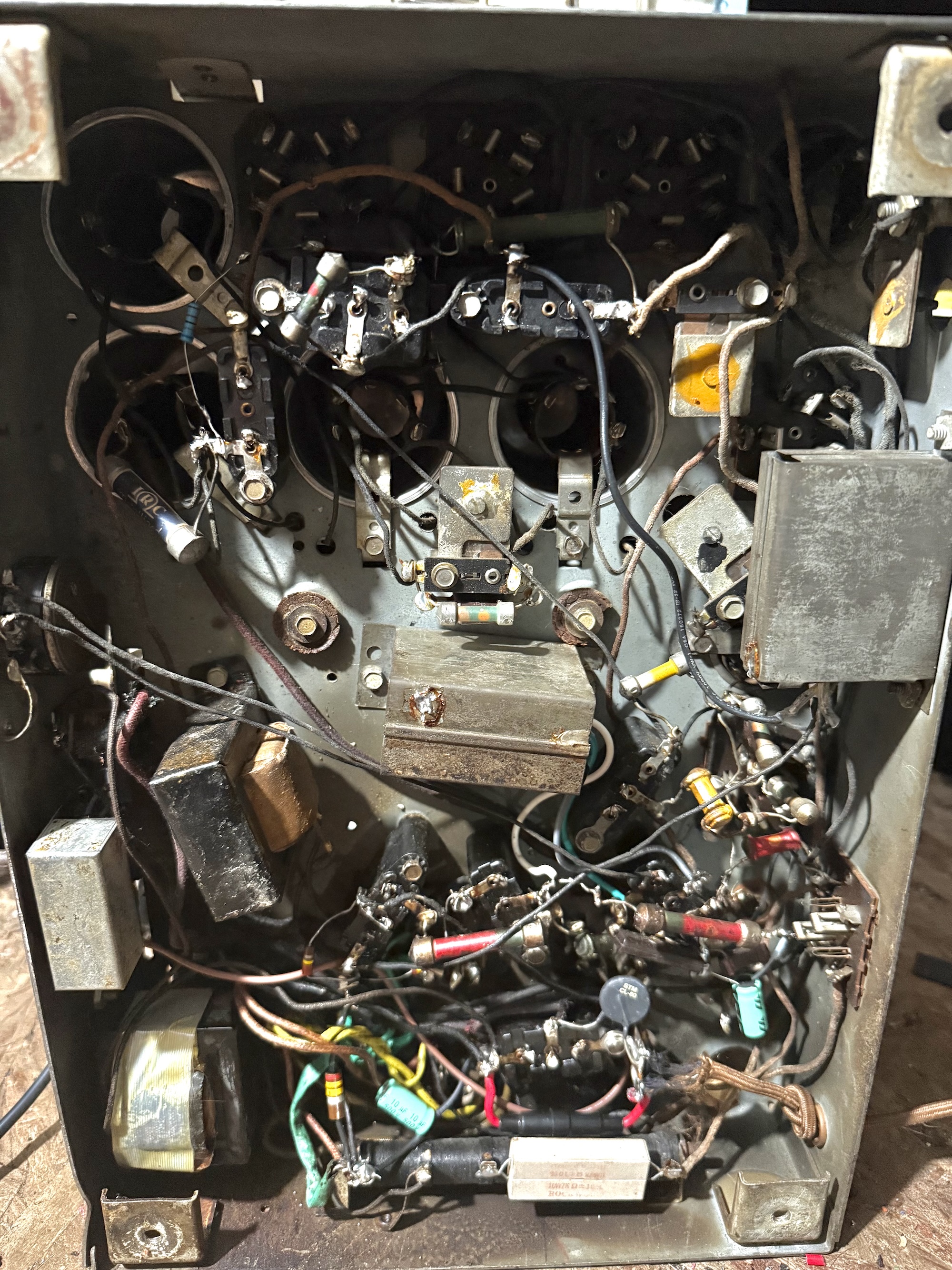
Sleeved some bare wire on the spacer near the plug. Tested the tubes - the 80 and 47 were marginal (and of course I don't have any extras, will have to order some). Powered it up and... no stations. Power supply and audio section is working, and there's no hum - so that's something.
Having dealt with open Philco coils in other sets, I thought I'd check some of the coils... and it looks like the primary of the 1st detector coil is open. I'm not the best at rewinding coils, but I had success with a Zenith field coil and a Philco 19 oscillator coil primary. On that set, I read that baking the coil in the oven after winding it was critical. I did that with good results. Worth doing for the 90 too?
Posts: 3,186
Threads: 226
Joined: May 2008
City: Omak
State, Province, Country: WA
Hello Adam,
Wow it's looking good so far and yes Philco's dreaded coils .
Sincerely Richard
Posts: 24
Threads: 8
Joined: Apr 2017
City: Weston, CT
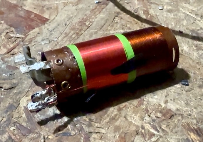
I managed to re-wind the coil. Didn't come out too badly. I removed the old winding along with the celluloid material, cleaned it with rubbing alcohol, and baked it in the oven at 200 for about 25 minutes. Then, I used green masking tape as an insulator, and I added roughly 100 turns of AWG 34 copper wire on it, and sprayed it with clear lacquer to protect it.
After reinstalling it in the radio I still had no reception. I used a little Emerson transistor radio to determine the oscillator was running. Trying to feed a 175kc signal into the antenna terminal resulted in a barely audible sound from the radio. I checked the voltages, and figured out that all of the screens in the front end were missing voltages - which they get through a 25k resistor, which, I had connected to the wrong terminal after redoing a bakelite block. Ugh! After fixing that, it plays.
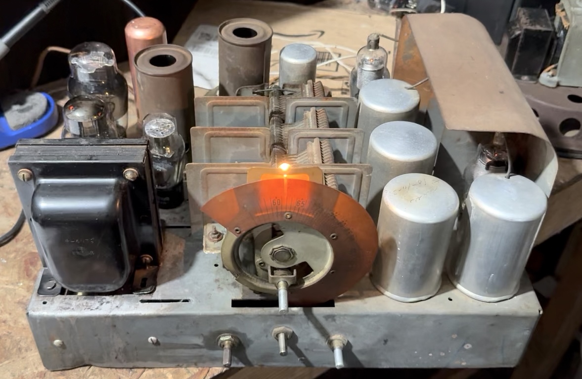
A couple things I noticed - it seems very sensitive and selective for an early radio. Tons of volume, but sound quality is only ok - I'm thinking due to the primitive speaker with a stiff spider. Also, voltages are all high - probably because of the replacement transformer. B+ at the rectifier is 310v, so I need to find a way to reduce that. I also noticed (how I missed this before, I have no idea), all tubes except for the 47 are 6.3v equivalents of the originals, obviously whoever worked on it had trouble finding a transformer with a 2.5v winding. I don't blame them for converting it over.
I tried to adjust the oscillator at 600kc, and found the adjustment didn't do much. I might just leave it, it works ok. I also really need to get grommets for the tuning capacitor, it's completely loose.
Posts: 3,186
Threads: 226
Joined: May 2008
City: Omak
State, Province, Country: WA
hello Adam,
Very nice !
Sincerely richard
Users browsing this thread: 1 Guest(s)
|
|
Recent Posts
|
|
Philco P45-6365 Universal Transformer Instruction Manual
|
| Can anyone guide me to where this may be found?GRG — 03:00 PM |
|
54C Complete Teardown/Rebuild
|
| I don't think that I have encountered a 12Z3 before, curious how it uses one of those but includes a #43, which is a 25 ...Arran — 02:17 PM |
|
HiFi (Chifi) tube amp build - but my own design.
|
| It's the other forum. I'm also in DIY, but mostly read there. Honestly, I kinda jumped into this without much thought to...TV MAN — 10:43 AM |
|
Philco 71 Code 125
|
| Hello,
I am in need of a schematic for this radio. Mine has the three separate circular tube shields and a shadow me...dconant — 08:06 AM |
|
Stromberg Carlson 1500 Squeal
|
| And life just keeps getting more complicated.dconant — 07:57 AM |
|
54C Complete Teardown/Rebuild
|
| Hello Roy,
here is this one
sincerely Richardradiorich — 12:45 AM |
|
54C Complete Teardown/Rebuild
|
| Richard,
Had grabbed it already but thank you just the same. I find myself wanting to find some way to block out the...glyphmon — 12:03 AM |
|
54C Complete Teardown/Rebuild
|
| Hello roy,
here is a link to the schematic .
Sincerely Richardradiorich — 11:54 PM |
|
54C Complete Teardown/Rebuild
|
| Richard,
The Silvertone 2014 also is a transformerless set, so I am incorporating a 1:1 600 ohm audio isolation transfo...glyphmon — 11:37 PM |
|
Preliminary work on wife's Silvertone 2014
|
| Did an alignment today which was interesting. IF alignment went great, almost all was already spot-on. Adjusting on th...glyphmon — 11:35 PM |
|
Who's Online
|
There are currently 2644 online users. [Complete List]
» 2 Member(s) | 2642 Guest(s)
|
|
|

|
 
|






