1953 Philco 53-T1886 Code 125 AM/FM/Phono/TV Combo
Posts: 374
Threads: 41
Joined: Dec 2019
City: Elkhart
State, Province, Country: Indiana
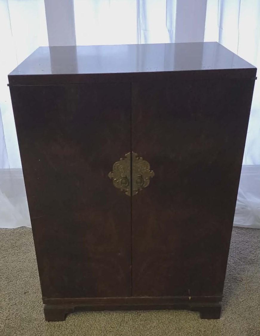
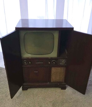
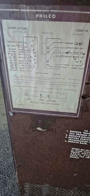
Hello Everyone, a friend of mine recently had a friend who passed away and he was helping his friend's widow go through her late husband's stuff and he bought for me a 1953 Philco Model 53-T1886 Code 125 AM/FM/Phono/TV Combo Unit that was something he had I guess bought years ago to restore, but I'm not sure if he ever got around to restoring it electrically or not or if it just sat around collecting dust.
I'm wondering if there's anything in particular I should look out for when attempting to restore this unit electricallly or if I should just go about working on this unit like I did with my old Meck/Philharmonic TV and just replace a few caps at a time and just test it out as I go? Was this TV known to drive tubes hard or was it easy on tubes? Also how was the flyback transformer on this set and the Hi-voltage section in general?
This is the first Philco TV from this time period I've ever worked on and so I'm not sure how the early Philco TVs are to work on compared to say Zenith or the Meck I previously Worked on thats from the same time period, I have worked on one other Philco TV, a Philco Townhouse, but that was from almost 15 years after this TV was made and so the chassis was quite a bit different.
See Photos Below.
Posts: 5,654
Threads: 56
Joined: Sep 2008
City: Sandwick, BC, CA
I can't recall reading anything outstanding about the reliability of Philco sets from this time period, the earliest models from the 1948-50 time period apparently had high voltage problems where the voltage would drop as the set ran. I'm not sure that this was a defect in the design of the flybacks or a result of lingering moisture inside the windings. I haven't heard much of anything about the 1953 models, good or bad, I believe that they still used point to point wiring, and had a proper power transformer, they were not series string, nor did the use an autotransformer. One advantage this has is that they obviously had settled on 21'' rectangular picture tubes by then, I think that they were either 45 or 60 degree, but are much more common then the earlier 17'' rectangular tubes, and were until the 110 degree tubes came out in the late 1950s.
Regards
Arran
Posts: 1,135
Threads: 54
Joined: Feb 2013
City: Shenandoah,
State, Province, Country: Pennsylvania
The only thing I could add would be to get a good set of Sams Photofact schematics for this unit!
Ron
Bendix 0626. RCA T64 Philco 20B
Philco 41-250. Philco49-500
GE 201. Philco 39-25
Motorola 61X13. Philco 46-420 Crosley 52TQ
Philco 37-116. Philco 70
AK 35 Philco 46-350
Philco 620B. Zenith Transoceanic B-600
Philco 60B. Majestic 50
Philco 52-944. AK 84
Posts: 3,188
Threads: 226
Joined: May 2008
City: Omak
State, Province, Country: WA
Hello captainclock1988 ,
myself I have a 12inch b/w bakelite set and far as Issues I agree with Arran .
Far as what Ron said Sams Photofact schematics you can't beat them it's a must .
hopefully these are good Picture, yoke,flyback !
Sincerely Richard
Posts: 374
Threads: 41
Joined: Dec 2019
City: Elkhart
State, Province, Country: Indiana
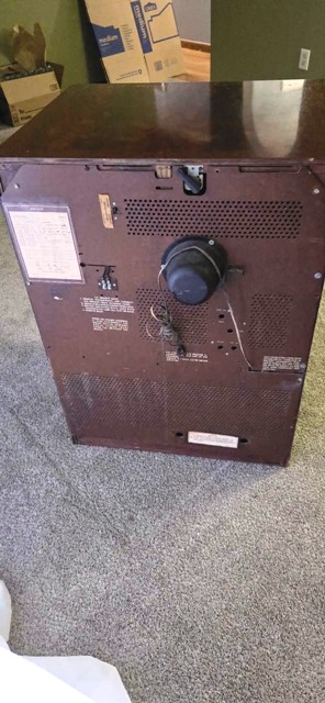
I picked it up today, and it says on the pencil-box cover Philco UHF on it, and there appears to be a 4-position bakelite knob on the back of the set and I'm wondering if that knob is supposed to be the UHF Knob? But the weird thing is that the VHF Tuner knob doesn't have a UHF Position, just Positions 2-13, I wonder if the UHF Tuner is triggered Independently of the VHF Tuner on this set?
Obviously the UHF Tuner working or not doesn't matter anymore because of Analog TV being no more but if I wanted to try and do something with a Blonder Tongue Modulator at some point in time that would be handy to have the UHF Tuner functionality.
This TV is not very big surprisingly enough, it only comes up to just below my waist height wise and width wise its only about a couple of feet, way smaller than my 2 color consoles I have.
Posts: 1,797
Threads: 55
Joined: Feb 2015
City: Roseville, MN
It's probably a converter that sends the signal to a VHF TV channel frequency.
Posts: 374
Threads: 41
Joined: Dec 2019
City: Elkhart
State, Province, Country: Indiana
It would make sense that it would be a converter of some sort, because inside the TV Cabinet it has a label saying "This TV has a provision for an internal installation of a Philco UHF Converter Model T-21 Only. Please refer installation to Factory Supervised Philco Technician." And that knob has a 300 Ohm twin lead with spade connections on it that look like they are meant to be attached to the VHF Antenna Terminals on the back of the TV, my guess is that the knob was preset/tuned to the UHF Stations available in your area (which would explain why it was a 4 position knob because when UHF first came out, there was usually only 2-4 UHF Stations in any given TV Market, and thats it, and it probably was designed to work on either Channels 2, 3 or 4, depending on what VHF stations were in use in your market.
This TV is extremely simple because unlike my John Meck Industries Inc. TV I restored several years ago that had almost 100 capacitors in it, this TV only has about 50 Capacitors or so between the radio, TV and Power supply/High Voltage circuits, also I was assuming this was a Hot Chassis set, because of how the radio and TV tuner circuits were wired up, but then when I pulled the power supply/high voltage/deflection circuitry it has a power transformer, which means this technically isn't a hot chassis set, because the power transformer is acting as an isolation transformer for both the radio and the TV Chassis.
Posts: 1,369
Threads: 94
Joined: Jan 2014
City: Annapolis, IL
State, Province, Country: USA
I have a similar model, actually a couple, just not a combo. Do a thorough visual. checking for chewed wires, missing tubes, other obvious things. I also suggest that if you have a CRT tester, test the big tube 1st. Good? Proceed, Dead? Well - not good. Be very careful removing the socket. I suggest prying apart gently with a screwdriver, cause you really want to keep the base on the tube rather than the socket. Don't panic if it doesn't register immediatly, it may need some time to "wake up". Yes, SAMS! Your roadmap!
Against what some may say, I usually do a slow powerup using a variac, dim bulb and isolation transformer. I like to see what's there before I start messing around. I usually pull the H-out tube cap to disable the HV. Take your time. That bulb will tell you the status of things, and you can increase the size and bring up the voltage as the caps reform and things come back to life. A short will illuminate the bulb brightly, if that happens (and it stays bright), then you got to check for shorts, the B+ caps, etc. Monitor B+ voltages and use that thing in the middle of your face to check for anything getting too hot. Feel the big caps, etc.
I DO NOT recommend shot-gunning caps, etc on a TV. Too much chance of making a mistake and then - where do you start? I get the power supply working halfway 1st, then move to the the horizontal to get HV and sweep, then usually the vertical, and finally a good going through on the rest of the set. Ya know, paper caps, electrolytics. 1 section at a time, try, it, work out any problems, then move on to another section. Keep the brightness down while starting cause more often than not, you wont have any vertical sweep or very little and you don't want to burn a nice dark line across your hard or impossible to find picture tube. Others may disagree, but I recommend watching a few Shango066 vids on YouTube when he brings up a sleeping set. Some don't like his techniques, but our troubleshooting methods are very similar, exc maybe I err on the side of being a little more cautious & thorough.
Edit: I also suggest a solid state replacement for your LV rectifier (5U4, etc) during the initial stages of your power up, since it'll send voltage to your caps at a lower setting when the tube wont conduct, however, don't go full power with it since it passes more voltage, switch back to the tube at about 75% since the tube will conduct then and gives some protection, a softer start, and puts your voltage closer to where it should be. I also suggest using a worn or 'beater' tube that you wont lose any sleep over if it gets blown, save the good one for the final. Just my 2 cents :-)
If I could find the place called "Somewhere", I could find "Anything" 
Tim
Jesus cried out and said, "Whoever believes in me , believes not in me but in him who sent me" John 12:44
(This post was last modified: 12-18-2025, 12:23 PM by TV MAN.)
Posts: 374
Threads: 41
Joined: Dec 2019
City: Elkhart
State, Province, Country: Indiana
Quote:I have a similar model, actually a couple, just not a combo. Do a thorough visual. checking for chewed wires, missing tubes, other obvious things. I also suggest that if you have a CRT tester, test the big tube 1st. Good? Proceed, Dead? Well - not good. Be very careful removing the socket. I suggest prying apart gently with a screwdriver, cause you really want to keep the base on the tube rather than the socket. Don't panic if it doesn't register immediatly, it may need some time to "wake up". Yes, SAMS! Your roadmap!
Against what some may say, I usually do a slow powerup using a variac, dim bulb and isolation transformer. I like to see what's there before I start messing around. I usually pull the H-out tube cap to disable the HV. Take your time. That bulb will tell you the status of things, and you can increase the size and bring up the voltage as the caps reform and things come back to life. A short will illuminate the bulb brightly, if that happens (and it stays bright), then you got to check for shorts, the B+ caps, etc. Monitor B+ voltages and use that thing in the middle of your face to check for anything getting too hot. Feel the big caps, etc.
I DO NOT recommend shot-gunning caps, etc on a TV. Too much chance of making a mistake and then - where do you start? I get the power supply working halfway 1st, then move to the the horizontal to get HV and sweep, then usually the vertical, and finally a good going through on the rest of the set. Ya know, paper caps, electrolytics. 1 section at a time, try, it, work out any problems, then move on to another section. Keep the brightness down while starting cause more often than not, you wont have any vertical sweep or very little and you don't want to burn a nice dark line across your hard or impossible to find picture tube. Others may disagree, but I recommend watching a few Shango066 vids on YouTube when he brings up a sleeping set. Some don't like his techniques, but our troubleshooting methods are very similar, exc maybe I err on the side of being a little more cautious & thorough.
Edit: I also suggest a solid state replacement for your LV rectifier (5U4, etc) during the initial stages of your power up, since it'll send voltage to your caps at a lower setting when the tube wont conduct, however, don't go full power with it since it passes more voltage, switch back to the tube at about 75% since the tube will conduct then and gives some protection, a softer start, and puts your voltage closer to where it should be. I also suggest using a worn or 'beater' tube that you wont lose any sleep over if it gets blown, save the good one for the final. Just my 2 cents :-)
I love Shango's videos, and yes, I agree, the way I tend to troubleshoot I partially learned from him and his videos, except for the fact that I don't use a dim bulb tester, I have an isolation transformer (a large 20# 350 VA unit, with 3 different voltage taps/outlets) and a Variac that was made by Powerstat, a model 116B.)
I do have a picture tube tester and I did test the picture tube, and the weird thing about my picture tube tester is that it has two different settings for the meter Normal and Special, and in Normal mode the picture tube doesn't respond to the tube tester, but in special mode the picture tube tests fine, the weird thing is that the picture tube filaments are glowing nice and bright, almost like brand new.
I removed the chassis out of the cabinet (all three of them) and looked at the underside of each of them, and they all look virgin yet, like they have never been worked on before, and the majority of the tubes (including the picture tube) are all the original Philco branded tubes, meaning this is more than likely a very low hours set, also I took a closer look at the radio tuning dial and it looks like its actually just AM (Broadcast) only, but I think if this set is anything like my Meck, or any of the other TVs from the 1950s, I think FM radio Reception can be achieved by Tuning the TV to Channel 6 and then turning the fine tuning knob to scan through the FM Broadcast Band.
I know that at least the Power Supply Filter Caps will need to be replaced, because the person I got this TV from plugged the TV in to show me it partially worked, and I heard the dead giveaway 60 Cycle Hum, come through the speaker. I quickly shut it off as soon as I heard that and had her unplug the set immediately.
This TV has mainly all Bumblebee capacitors in it, which I thought Zenith was the main company at that time that used those in their electronics, but I guess Philco loved them too.
Posted by captainclock1988 - 12-08-2025, 12:56 AM
Posts: 1,369
Threads: 94
Joined: Jan 2014
City: Annapolis, IL
State, Province, Country: USA
Sounds like a pretty nice set! If it's all original, it's probably a low hour. Not sure what to tell you on the tube test, My testers don't have that, but have a bunch of other stuff. It does sound promising tho. There are current limiting power supplies. I think Bob Anderson uses one. A dim bulb isn't hard to make. Just a cord with a socket in series on one leg. I made one similar to Shango with the bypass switch.
Def need to get rid of those firecrackers (Bumblebees), but I've brought 'em up with them before. Snip out the "death cap", across the AC line. But, beingstho its been powered up already, hum means open caps. You could jump them and do a slow powerup to see what you have. Again, keep the brightness turned way down in case (likely) you don't have vertical sweep. Sneak it up slowly if you have HV and see what you have.
If I could find the place called "Somewhere", I could find "Anything"
Tim
Jesus cried out and said, "Whoever believes in me , believes not in me but in him who sent me" John 12:44
Posts: 374
Threads: 41
Joined: Dec 2019
City: Elkhart
State, Province, Country: Indiana
Quote:Sounds like a pretty nice set! If it's all original, it's probably a low hour. Not sure what to tell you on the tube test, My testers don't have that, but have a bunch of other stuff. It does sound promising tho. There are current limiting power supplies. I think Bob Anderson uses one. A dim bulb isn't hard to make. Just a cord with a socket in series on one leg. I made one similar to Shango with the bypass switch.
Def need to get rid of those firecrackers (Bumblebees), but I've brought 'em up with them before. Snip out the "death cap", across the AC line. But, beingstho its been powered up already, hum means open caps. You could jump them and do a slow powerup to see what you have. Again, keep the brightness turned way down in case (likely) you don't have vertical sweep. Sneak it up slowly if you have HV and see what you have.
The Picture tube Tester I have is a B & K Picture Tube Tester Model 453 which I have all of the paper work for it but it doesn't really do a good job at explaining the Normal vs. Special switch settings for the meter and what tubes it should be used on.
I did get a Sam's Folder Ordered for this TV, and I also have the Sam's Folder for the Record player portion of the TV as well.
The Radio Chassis portion of the TV just has 4 capacitors in it, and I don't think it will be too hard to repair that. the TV's RF/IF section has about 15 capacitors and that shouldn't be too hard to do, its the Power Supply/Sweep/HV section that's going to be a little trickier to do, because it has about 2 dozen bumblebee caps, and then 3 can caps (of which 2 of the can caps are single section units and one is a 3 section unit) and then it has 2 large Selenium Rectifiers which I am guessing will need to be replaced with Silicone Diodes of some sort (probably something larger than 1N4007s).
The Cabinet has beautifully grained Mahogany, and it has the old "Oriental" style cabinet Pulls (like the ones you find on old Chinese and Japanese Furniture.)
Posts: 1,369
Threads: 94
Joined: Jan 2014
City: Annapolis, IL
State, Province, Country: USA
Ah, a recappers dream  I used a bridge to replace the big selenium rectifiers on my Craftsmen. Worked fine. I did power it up with the old rectifiers, it worked then changed them later. I DON'T recommend messing with the IF on either, unless you find you have a problem, especially the TV. You'll end up with an alignment nightmare! Leave it alone.\ The radio isn't as tricky, but normally just a little touch up and you're golden. Usually they have mica, disc and ceramic caps and are ok, and that is what you should have in the IF section. Yes, there are exceptions. E caps? Yes, replace 'em. Paper/Bumblebees? Same. Replace. Could be a few "postage stamps" that look like micas and those need to go too. Glad the cabinet is good. That is about as much a deal breaker as the big tube!
If I could find the place called "Somewhere", I could find "Anything"
Tim
Jesus cried out and said, "Whoever believes in me , believes not in me but in him who sent me" John 12:44
Posts: 1,135
Threads: 54
Joined: Feb 2013
City: Shenandoah,
State, Province, Country: Pennsylvania
+1 on what Tim is telling you, especially about messing with the TV IF section. Back in the 70s I worked at a TV/Appliance dealership. One time we had an RCA color set in the shop and the cable reception in our shop was horrible. The owner’s brother was a retired RCA engineer who happened to stop in on the shop. He saw what I was working on and said..oh an RCA, one of my babies.. and proceeded for over an hour to twiddle every IF adjustment trying to compensate for the lousy cable. Finally, he said that’s the best it’s going to get and left me with the mess. I told the boss what his brother did and we had no sweep generator or any signal generator for that matter to even attempt an alignment. We had no choice but to return it to the customer. Never did hear if the boss heard any complaints from that customer.
Ron
Bendix 0626. RCA T64 Philco 20B
Philco 41-250. Philco49-500
GE 201. Philco 39-25
Motorola 61X13. Philco 46-420 Crosley 52TQ
Philco 37-116. Philco 70
AK 35 Philco 46-350
Philco 620B. Zenith Transoceanic B-600
Philco 60B. Majestic 50
Philco 52-944. AK 84
(This post was last modified: 12-21-2025, 09:20 AM by 462ron.)
Posts: 374
Threads: 41
Joined: Dec 2019
City: Elkhart
State, Province, Country: Indiana
I'm definitely not planning on touching the IF controls on this TV, I learned my lesson the hard way when I was working on my Meck Philharmonic Model 8200 TV that still doesn't really work quite right that you shouldn't touch those IF Pots unless you have the right alignment gear (which I still don't have the correct alignment gear for doing Video IF Alignments.)
I will though be replacing all of the old Capacitors (all of them are old Sprague Bumblebee Caps) and all of the old electrolytics cans with modern axial leaded electrolytics that will be attached under the chassis while leaving the original cans ontop of the chassis for appearance sake.
I was able to test all of the tubes for the TV, and radio chassi and all of the tubes except for about 5 of them tested like brand new yet including many of the original Philco branded tubes with a date code of 43rd week of 1952 (which fits with my idea of this TV being from 1953.)
Posts: 374
Threads: 41
Joined: Dec 2019
City: Elkhart
State, Province, Country: Indiana
I was compiling a parts list for my TV/Radio/Record Player combo unit, and there are several electrolytic capacitors that are values that I don't know if I can get them without having to put several capacitors in parallel or in series (which ever one will double the voltage but keep the capacitance value the same) The coupling/bypass capacitors which are the paper/bumblebee caps are all normal 200-600 volt capacitors which can be replaced with 600 or 630 volt capacitors but the electrolytics are really odd values that are 500V or higher with one being rated at 2kV and one being rated at 4kV and when I looked through Mouser and Digikey the highest the electrolytics went voltage wise was 600V so I'm guessing what I will need to do is get 4 500V capacitors and tie them together to get the 2kV and then get 8 500V capacitors and tie them together to make the 4kV, but I can't remember if its series or parallel that keeps the capacitance the same and doubles the voltage. Would what I laid out work?
Thanks for your help.
Users browsing this thread: 1 Guest(s)
|
|
Recent Posts
|
|
Plug Voltages Needed For A 1943 CRV-20130 Power Supply
|
|
That looks a lot like an aircraft connector of some kind ...
That is a MIL-5015 style connector, used in a wide v...DaleHCook — 10:19 AM |
|
Philco P45-6365 Universal Transformer Instruction Manual
|
| I would suggest changing the topic from "P45-6365 Universal Transformer" to "45-6365 Universal IFT."...DaleHCook — 10:08 AM |
|
Stromberg Carlson 1500 Squeal
|
| And life just keeps getting more complicated. By dconant.
Dittos'Jimradio — 08:01 AM |
|
Plug Voltages Needed For A 1943 CRV-20130 Power Supply
|
| That looks a lot like an aircraft connector of some kind, even if it's a U.S.N power supply. I have a book somewhere abo...Arran — 02:56 AM |
|
Plug Voltages Needed For A 1943 CRV-20130 Power Supply
|
| hello david,
I have a similar generator in my collection that features a cast iron, single-cylinder Briggs & Stratt...radiorich — 01:00 AM |
|
under chassis parts locator diagram for 1938 Zenith 9s262
|
| Has anyone gone to the trouble of creating an under chassis parts locator image? Yes, I can identify components by foll...bobloney — 08:57 PM |
|
Plug Voltages Needed For A 1943 CRV-20130 Power Supply
|
| Try looking at this site the book mark is for a old generator that I was given. David https://radionerds.com/index.ph...David — 08:36 PM |
|
Plug Voltages Needed For A 1943 CRV-20130 Power Supply
|
| Hello Everyone,
I am looking for voltage identification for all the pin positions on the socket of a CRV-20130 power su...Tonym4704 — 08:16 PM |
|
Philco P45-6365 Universal Transformer Instruction Manual
|
| Can anyone guide me to where this may be found?GRG — 03:00 PM |
|
54C Complete Teardown/Rebuild
|
| I don't think that I have encountered a 12Z3 before, curious how it uses one of those but includes a #43, which is a 25 ...Arran — 02:17 PM |
|
Who's Online
|
There are currently 1738 online users. [Complete List]
» 1 Member(s) | 1737 Guest(s)
|
|
|

|
 
|