42-327 heater circuit confusion
Posts: 2,327
Threads: 23
Joined: Jul 2020
City: Greenlawn
State, Province, Country: NY
Is the 80 ohm resistor in this set? according to the schematic, it should not be.
The design of rectifier tubes and circuits for AC-DC radios is rather interesting. The 35Z5 and later 35W4 had an interesting, tapped heater. This heater was designed to have a load of an indicator lamp in parallel with the tap on the heater, between pins 2 and 3, dropping 7.5V across this junction at the proper current. The draw of that section and the indicator in parallel with it is supposed to be 150 mA. Interestingly, in addition, usually, the input to the plate for this circuit was also on the tap. This allowed the heater and indicator to act as a fuse (albeit a rather expensive one). In case of a short or other cause of overcurrent, the heater of the 35Z5 or 35W4 and the indicator would burn out. In addition, an open indicator lamp could possibly shorten the life of the tube. A WWII hack when these tubes may not have been available to civilians due to rationing, was to bypass the "tap" section by bridging pins, thereby restoring operation, albeit at a slightly higher voltage across all heaters.
None of this exists in sets with the 35Z3, 35Z4 or solid state rectifier., including the fusing function. Therefore, I don't know how they dealt with fusing without the heater tap, resistor or actual fuse.
Post-war, Philco switched from the Loktal 35Z3 to the octal 35Z5. They then switched from the 50L5 to the Loktal 50A5. I believe that Sylvania invented the Loktal tube for Philco and possibly Motorola, as these were the 2 major innovators of Auto radios and had the most interest in Loktal tubes. In addition, Loktal tubes possibly represented increased manufacturing efficiency as having the pins integral to the tube eliminated the stap of soldering leads from the tube to the pins of a base that had to be manufactured and then glued to the tube, then the pins soldered. Loktal tubes appeared in around 1940, around the same time that the first miniature tubes for VHF and battery radios appeared. Loctal tubes were supposed to be an innovation, but it seems that for many of us, we see flaws in that innovation.
2 "mods" to consider would be to install a 0.4A fuse for shorts protection and a "globar" resistor to mitigate the "surge" in the heater string when first turned on. Tube heaters have a much lower resistance when cold than when hot. This explains why the indicator light on sets with 35Z5 / 35W4 tubes and indicators in the string will glow extremely bright, dim, then get to designed brightness, and eventually burn out. On the 122 version of this set, this is not as much of an issue, as the indicator is a 120V bulb. 3W indicator bulbs are still available and may be available at Home Depot, but definitely available on the internet. LED versions ot the "C7" nightlight / Christmas tree bulb is commonly available.
"Do Justly, love Mercy and walk humbly with your God"- Micah 6:8
"Let us begin to do good"- St. Francis
Best Regards,
MrFixr55
Posts: 20
Threads: 2
Joined: Oct 2025
City: Springfield
State, Province, Country: Missouri
I did get it wired with power to the heaters but most of the tubes are not getting the voltage they should. The 35Z3 is at 29v and the 50L is at 42 the others are a little low as well. I might have a miswire but there is many wires to replace even though I’m not seeing any obvios shorts it’ll be more important to rewire before getting power fine tuned.
Posts: 1,797
Threads: 55
Joined: Feb 2015
City: Roseville, MN
I've been following along on the progress. The heater string is separate from the rest of the wiring but there could be a short from one of the other wires to the heater string. Any short within the heater string would more than likely cause the voltages to be higher than normal.
Posts: 20
Threads: 2
Joined: Oct 2025
City: Springfield
State, Province, Country: Missouri
I have wires that could short until I replace them, so I’m not powering the radio until I go through more of the replacements. There are a couple of resistors that read high and that’s disconnected circuit checks. I think they are 1w resistors. About half inch long and quarter inch diameter. Philco doesn’t list power specs in the parts list. With the storm coming in I will have time to rewire more. Still no sign of an 80 ohm resister not measured or seen.
(This post was last modified: 01-23-2026, 09:47 PM by SlidesK.)
Posts: 18,427
Threads: 622
Joined: Oct 2011
City: Jackson
State, Province, Country: NJ
So. Direct question: you do not see a Candohm resistor on the left internal side of the chassis (denpted with red arrow below)? Nor do you see the signs of it being there before?
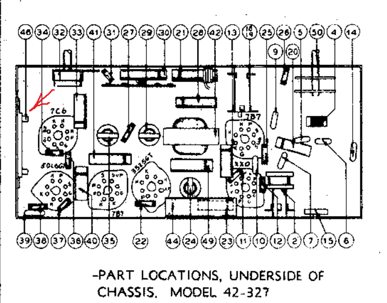
Also: Could you summarize teh state of the radios? I am confused a bit: do you have now power to teh heaters or have you wired them separately to check the tubes but it is not like it is supposed to be wired?
People who do not drink, do not smoke, do not eat red meat will one day feel really stupid lying there and dying from nothing.
Posts: 20
Threads: 2
Joined: Oct 2025
City: Springfield
State, Province, Country: Missouri
Hi morph, I do not see any sign of a resistor that would be in the heater circuit. There are holes in the chassis where your pointer is but not even a scratch showing it might have been removed. I followed the tube lineup in the heater diagram starting with 35Z3 to 50L6 and checked each combination of pin connections to map and verify the circuit. From pin 1 to 7 on 35z to 50L no resistor and other combinations between them until I mapped the circuit through to pin 8 of XXD to B- then I added a wire from pin 8 on XXD where it shows B- to the circuit at the volume control at the 4.7meg resistor. I wired the lamp as suggested in the thread and now I have voltage to the tube filaments that is a little lower that it should be. Then a quick check of B- to B+ on both sides of the coil showed 130v instead of 108v and 88v instead if 83v. I quickly checked the AC across each heater to find all of them read a little lower than I expected. I turned it off so I can go back to tracing the circuits and replacing any suspect parts and crumbling wires before powering it again. At one point the B+ was too low and that’s when I added the B- The only tubes that get hot are the rect and output the rest just a little warm or cold. So my plan is to trace and replace all questionable wires and parts before going forward. The cans all measure good the speaker measures within tolerance 240 of 250 and the field coil is at 470 of 500. Hope this helps answer your question.
Posts: 5,652
Threads: 56
Joined: Sep 2008
City: Sandwick, BC, CA
No there isn't an 80 Ohm candohm resistor in the versions with the 35Z3s, which I don't understand since it is in series with the heater string in the code 121 version. I thought that maybe it was in parallel with part of the heater for the 35Z5, it was quite common to do that in sets with the 6.3 volt pilot lamps.I would guess that the majority of resistors were either 1/4 to 1/2 Watt, and the larger ones being 1 or 2 Watts.
Regards
Arran
Posts: 18,427
Threads: 622
Joined: Oct 2011
City: Jackson
State, Province, Country: NJ
Well..a suggestion (feel free to disregard).
Try to draw the filament power string from the actual chassis (not from the sch).
Just the filaments. The sign of completion: there should be an uninterrupted link with the power plug, switch and the filaments in between.
Also include: whatever between the filaments (in series) and whatever not in series, but just connects to them.
People who do not drink, do not smoke, do not eat red meat will one day feel really stupid lying there and dying from nothing.
Posts: 2,327
Threads: 23
Joined: Jul 2020
City: Greenlawn
State, Province, Country: NY
Hi SlidesK,
Follow Morzh's advice, visually trace the wiring and draw a schematic of what you see. Remember, for all tubes except the 50L6, the heater connections are pins 1 and 8. This includes the 35Z3. For the 50L6, the heaters are on pins 2 and 7. I verified this for each tube in your set against the RCA receiving tube manual, Rev RC13, published 1940 (or so)
The pictorial of the underside chassis layout is for the Code 121 set with the 35Z5 rectifier. If I am right, sets with the 35Z3 will not have the Candohm 80 Ohm resistor.
Are you using the dimbulb tester when you are making the voltage measurements for the heaters? If so, the heater voltages will be low because there will be a drop across the dim bulb.
The way the Code 122 set is supposed to be wired, there is no resistor in the heater string, therefore, there should be 35V across the 35Z3 heater, 50V across the 50L6 12V across the XXD and 6V across the rest of the tubes for a designed line input of 115V. You should actually see a little higher as most power is about 120V these days.
Check across the power line between Pins 1,2 of the 35Z3 and the power switch. Chack both sides of the switch to determine if there is a voltage drop across the switch. There should not be. If you receive 115-125V there but are having these low heater voltage readings, then something is wrong. You may have a bad connection somewhere, but by this time, you should be hearing something from the radio.
Good luck and keep posting. You will get this going!!
"Do Justly, love Mercy and walk humbly with your God"- Micah 6:8
"Let us begin to do good"- St. Francis
Best Regards,
MrFixr55
Posts: 18,427
Threads: 622
Joined: Oct 2011
City: Jackson
State, Province, Country: NJ
Yeah...I also had the impression that the dim bulb was being used.
Mr. Fixr is right. You cannot use it for measurements. Only for initial power-up, to prevent the short being powered from AC.
If you have found out you have no short, use a Variac or an isolating transformer but do put at least 110-115VAC to it.
You could do it briefly (I do, 3-5 seconds), observe no spark, turn off, give it a good whiff, smell no burn, turn it for longer, see no smoke, after 10-15 s turn off, make sure the input caps are discharged, feel for heat.
If OK, turn ON and keep working.
People who do not drink, do not smoke, do not eat red meat will one day feel really stupid lying there and dying from nothing.
Posts: 20
Threads: 2
Joined: Oct 2025
City: Springfield
State, Province, Country: Missouri
Ok yea I'm still here and reading your comments. I got most of the wiring replaced and found a short that just popped up when I was checking the power. It wasn't disastrous but glad it showed itself without trouble. Fixed that and rewired one of the cans with good results. Last checked I have 116 volts on the heater string but 122 on the B+ s/b 108, other voltages are a little off and ranging a few volts, mostly high. There are a couple of resistors that are out of specs that I'll have to order because they are bigger and I'm guessing 1 watt. with the B+ higher than it should be I wasn't on for long but long enough to do a quick sound check for the 50L and the hum was clear with static on the speaker, without an antenna. So aside from tracing and studying the bad resistors and what they do while I wait for the replacements I think Ill turn my attention to the Zenith J615 that seems to have a AVC problem and maybe SMD as well, but that is for another thread. Thanks for all the helpful comments and I will keep you all updated.
Posts: 2,327
Threads: 23
Joined: Jul 2020
City: Greenlawn
State, Province, Country: NY
Hi SlidesK,
Sounds like you are making good progress.
Most resistors in these sets are half watt. the old carbon resistors look bigger than the newer metal film ones. The only place where you might need a 1 watt resistor is the cathode resistor for the 50L6.
Re the 120V B+, this may be due to low current draw. if there was no current draw on B+ due to a wiring issue, a bad output tube or a bad cathode resistor for that output tube, the B+ will be higher. It could be as high as 140V if no current was drawn.
Did you measure 120V at the cathode of the rectifier? Measure on the other side of the field coil, at the junction of the speaker field, 20 uF cap, Output transformer, etc. If much less than 83V, then you may have an incorrect speaker or there is a problem with the field coil. However, field coils either short, causing a low resistance or open causing infinite resistance.
The biggest draw on the power supply is the output tube. The output tube in these sets is bias for "Class A", where the current is rather constant between minimum volume and maximum volume. For a 50L6 at 100V, the plate current at minimum power output is 49mA. At maximum output, it is 50mA. The diagram calls for a 130 Ohm resistor.
A resistor is good if it is within 20% of specified value. If "pregnant" or cracked, then change it out even if the reading is good.
"Do Justly, love Mercy and walk humbly with your God"- Micah 6:8
"Let us begin to do good"- St. Francis
Best Regards,
MrFixr55
Posts: 20
Threads: 2
Joined: Oct 2025
City: Springfield
State, Province, Country: Missouri
Both sides of the field was high as well as the output plate and a couple other quick checks were high at the plates. There is a 2200 ohm resister that measured 2900 and a 15k that measured 18k that might just be bigger 1/2 watt. If so I have replacements. The 130 ohm might be 1 watt but it’s not far off at 135. The 2200 is on the XXD tube maybe the grids bias. Can’t remember off hand
Posts: 2,327
Threads: 23
Joined: Jul 2020
City: Greenlawn
State, Province, Country: NY
Try to play the radio. Hum should be quite low..If you can tune in a station, it should be loud. If the volume is low, check or replace the 50L6. If the tube's emission is low, this could cause the voltage to be high. Had this happen to me on a Gloritone Model 26. Low volume, voltage 50V too high. Replaced the output tube (a 45), problem gone. Plenty of output, correct voltages.
"Do Justly, love Mercy and walk humbly with your God"- Micah 6:8
"Let us begin to do good"- St. Francis
Best Regards,
MrFixr55
Posts: 20
Threads: 2
Joined: Oct 2025
City: Springfield
State, Province, Country: Missouri
Arran, it was the 121 code that included the 80 ohm line resistor in the heater string. I’m working on the 122 code with a 35z3 rectifier. I’m getting about 116v on the heater string now. My measurements are taken with the variac supplying a line voltage of 117v without the dim bulb. Somewhere I saw the measurements of the old carbon 1/2 and 1 watt resistors. So I got out my caliper and now can’t find the thread. Anyone have those measurements?
(This post was last modified: 01-26-2026, 03:37 PM by SlidesK.)
Users browsing this thread: 1 Guest(s)
|
|
Recent Posts
|
|
Philco P45-6365 Universal Transformer Instruction Manual
|
| Can anyone guide me to where this may be found?GRG — 03:00 PM |
|
54C Complete Teardown/Rebuild
|
| I don't think that I have encountered a 12Z3 before, curious how it uses one of those but includes a #43, which is a 25 ...Arran — 02:17 PM |
|
HiFi (Chifi) tube amp build - but my own design.
|
| It's the other forum. I'm also in DIY, but mostly read there. Honestly, I kinda jumped into this without much thought to...TV MAN — 10:43 AM |
|
Philco 71 Code 125
|
| Hello,
I am in need of a schematic for this radio. Mine has the three separate circular tube shields and a shadow me...dconant — 08:06 AM |
|
Stromberg Carlson 1500 Squeal
|
| And life just keeps getting more complicated.dconant — 07:57 AM |
|
54C Complete Teardown/Rebuild
|
| Hello Roy,
here is this one
sincerely Richardradiorich — 12:45 AM |
|
54C Complete Teardown/Rebuild
|
| Richard,
Had grabbed it already but thank you just the same. I find myself wanting to find some way to block out the...glyphmon — 12:03 AM |
|
54C Complete Teardown/Rebuild
|
| Hello roy,
here is a link to the schematic .
Sincerely Richardradiorich — 11:54 PM |
|
54C Complete Teardown/Rebuild
|
| Richard,
The Silvertone 2014 also is a transformerless set, so I am incorporating a 1:1 600 ohm audio isolation transfo...glyphmon — 11:37 PM |
|
Preliminary work on wife's Silvertone 2014
|
| Did an alignment today which was interesting. IF alignment went great, almost all was already spot-on. Adjusting on th...glyphmon — 11:35 PM |
|
Who's Online
|
There are currently 1675 online users. [Complete List]
» 1 Member(s) | 1674 Guest(s)
|
|
|

|
 
|








