89B Code 123 revisited...
Posts: 20
Threads: 3
Joined: Aug 2024
City: Orange
State, Province, Country: CA
Hi, I made some progress on an 89B Code 123 about a year and a half ago, other things got in the way and I had to shelf this project for a while. I got as far as finding a new speaker, reworking the power supply, full recap and replacing resistors. I have worked on a bunch of AA5 radios, this is my first 30s Philco...
I rewound the oscillator coil which I thought would be the final task, put it in place and fired it up... only to get a constant 800hz to 1khz tone depending on how I tune the variable cap. I think this sound was there when I tested the radio after doing everything but the oscillator coil, so I'm not sure the oscillator coil is causing the issue. This is when I ran out of time for this project.
However, looking at this chassis now, I'm not sure I wound the coil correctly at all. If I'm reading the schematic correctly and testing the correct leads on the coil, the primary is open. However, I'm not sure I'm checking this correctly. It's part 7 in the service bulletin 146B.
Does anyone have some troubleshooting tips to 1) check if I've rewound the coil correctly or made a mess of it, and 2) help to track down the source of the oscillation? Several of the screen grids are tied together which makes it difficult to pinpoint where the oscillation is coming from.
On a positive note I did go back and double check all the work I did and found that I had used a 5K resistor where the schematic called for a 50K. So that's something!
Thanks,
Kurt.
Posts: 18,427
Threads: 622
Joined: Oct 2011
City: Jackson
State, Province, Country: NJ
Checking for an open primary coil is super-easy.
Either take an Ohmmeter (after you power off) or measure the voltage (when powered on) at the respective tube's plate relative to GND. If it is very low or 0V, it is open. If not, it is not open.
People who do not drink, do not smoke, do not eat red meat will one day feel really stupid lying there and dying from nothing.
Posts: 20
Threads: 3
Joined: Aug 2024
City: Orange
State, Province, Country: CA
The plate of the 44 IF tube to ground is 94K, which makes sense because it’s going through #18 @ 5K, #30 @ 39K and #31 @ 50K. So that’s good!
The two leads (that aren’t connected to ground or the primary of #15 the 1st IF transformer) give me around 2.0Ω and 2.5Ω to ground so maybe I wired that coil correctly after all!
Posts: 18,427
Threads: 622
Joined: Oct 2011
City: Jackson
State, Province, Country: NJ
Just see if you have oscillation. Either scope or another radio. This way you'll know.
Your conenction to GND is not that important. Your plates through their respective loads (the primaries of the RF xfmrs) are connected to the B+ bus that goes through the 1125 Ohm field coil to the cap #37 and the rectifier output.
This is what produces the voltage. The 39K and 50K resistors are the SG bias.
People who do not drink, do not smoke, do not eat red meat will one day feel really stupid lying there and dying from nothing.
Posts: 2,327
Threads: 23
Joined: Jul 2020
City: Greenlawn
State, Province, Country: NY
I worked on an 89 a few years ago, definitely not one of my favorite sets. The biggest problem in this set is the "Autodyne" first detector ("Oscillator Mixer" or "Convertor)" stage. Although this type circuit is used in other sets such as the 80, it is particularly troublesome in this set.
Note that there are 2 transformers in the plate circuit of the convertor tube. One is the oscillator transformer, #11 on the diagram. This transformer has 3 coils; the primary in the plate circuit; the secondary having the oscillator tuning; and the "tickler" in the cathode circuit that causes oscillation. The "Primary" of this transformer is in series with the primary of the 1st IF transformer, #15 on the diagram.
First off, ensure that the grid cap wire for the 1st AF tube is within the shield and that the speaker wires are away from both the 1st AF tube and the output tube.
Second, ensue that Cap #17, the AVC filter is correctly installed. It is a 0.09uF cap. You can use a 0.1uF cap. This cap smooths the negative audio signal into a DC component to bias the RF and IF amps. Failure of this cap will cause much funkiness such as motorboating or oscillation.
Third, ensure that all bypass caps are correctly installed, especially those caps that are between the screen grids or the RF and IF tubes and ground. Do not just "bridge" the caps that are i the bakelite bocks or the 4 caps in the metal contai9ner you must remove the old caps from the circuit.
Fourth, remove the grid cap from the IF tube. Does the oscillation stop? If no, troubleshoot this stage and the audio stage.
Fifth, pull the RF amp tube. Any difference?
Sixth, Touch the grid cap of the convertor (1st detector) tube. Does the squealing stop? If so, concentrate on that stage. If not, remove the tube. Does it stop now?
One problem when rewinding the "tickler" of the oscillator is winding it backwards. If so, i believe that you can revere the tickler connections to make it work. Most problems rebuilding this coil will prevent the convertor from correctly oscillating. So, either it oscillates or not.
Unfortunately, neither the Philco diagram nor the Breitman diagram from the Nostalgia Air website have pin diagrams for the coils.
Here is a link to articles from Ron Ramirez (God rest this good man's soul) on the 89.
https://philcoradio.com/library/index.ph...-model-89/
Hope this helps.
"Do Justly, love Mercy and walk humbly with your God"- Micah 6:8
"Let us begin to do good"- St. Francis
Best Regards,
MrFixr55
Posts: 18,427
Threads: 622
Joined: Oct 2011
City: Jackson
State, Province, Country: NJ
I worked on a 19LZX. 19 and 89 are more or less the same radio.
I concur as to the likability of the radio. I think it has that extra board...I also think 45 has such a board. Hated it.
People who do not drink, do not smoke, do not eat red meat will one day feel really stupid lying there and dying from nothing.
Posts: 20
Threads: 3
Joined: Aug 2024
City: Orange
State, Province, Country: CA
Quote:Third, ensure that all bypass caps are correctly installed, especially those caps that are between the screen grids or the RF and IF tubes and ground. Do not just "bridge" the caps that are i the bakelite bocks or the 4 caps in the metal contai9ner you must remove the old caps from the circuit.
Made it through the first two steps, then went back and found a .01 cap when I should have used a .0015 cap. Problem solved! I took a lot of care in cleaning out those blocks. Didn't mind that compared to that oscillator coil. Glad I was successful on that, don't relish doing another...
Quote:I think it has that extra board...I also think 45 has such a board. Hated it.
Agreed, I have a 45 butterfly but after looking at a Ron Ramirez post on that radio I think I'll get a few more Philcos under my belt before I try that one...
After replacing that cap I was able to align it and pick our strongest local station without an antenna. That's pretty good! I think I'm hearing a volume increase, every couple of minutes the set gets louder, then a minute later it dips in volume. My garage has a lot of what I think is switch mode noise so I'll have to take it inside and try it in a better listening environment to be sure. I don't know of a way to filter that noise other than just moving away from it.
Thanks for the help!
Posts: 20
Threads: 3
Joined: Aug 2024
City: Orange
State, Province, Country: CA
BTW, what's the recommended wire for running from the chassis to the speaker? Right now I have some 600V stranded with but it's modern and doesn't look that good. Not the most important part of the radio, but might as well make it look more or less period correct from the back as well as sound good...
Posts: 18,427
Threads: 622
Joined: Oct 2011
City: Jackson
State, Province, Country: NJ
You do need at least 200V-rated wire as the speaker has the transformer on it.
So...Radiodaze has cloth-covered wires, the thinnest, I think, is either AWG20 or 22, forgot. Should do if it satisfies your aesthetics.
People who do not drink, do not smoke, do not eat red meat will one day feel really stupid lying there and dying from nothing.
Posts: 553
Threads: 89
Joined: Jun 2022
City: Marion
State, Province, Country: NY
Hello Kurt. I have done several Philco 89s radios that use the 75 tube. That tube turned out to be the volume up down issue you have and I had. Reflow the grid cap on that tube and maybe your problem will go away as it did for me. Or maybe clean out the solder and scrape the wire sticking up then re solder. Don't leave the iron on too long.
I have done a Philco 45 (lowboy) too and I hated those boards too.
Dan
Posts: 20
Threads: 3
Joined: Aug 2024
City: Orange
State, Province, Country: CA
Quote:So...Radiodaze has cloth-covered wires, the thinnest, I think, is either AWG20 or 22, forgot. Should do if it satisfies your aesthetics.
OK, thanks for the tip! Any suggestions on the speaker connector plug? This set didn’t have one, and I’m looking for a quick release kind of connector so in the future I won’t have to take the speaker out if I have to remove the chassis.
Quote:the 75 tube. That tube turned out to be the volume up down issue you have and I had.
The wire to the grid cap was a little suspicious, kind of cracked so I replaced it and cleaned out the grid cap and the connector to the grid cap and it seems like the issue is gone. Really starts to oscillate if the lead gets too close to the adjacent tube! I'll try reflowing the cap if I hear it again.
This set is really noisy still. I see that there's 35VAC in kind of a triangle wave on the first filter cap but only .3mV on the second, so hopefully that's OK. I guess I could bump up the values a little since they're both only 8µf which seems a little low from my (very limited) experience. Maybe lower value caps were cheaper back in the day?
I haven't had a radio yet that was still this noisy even when tuned in on a strong station. A new troubleshooting opportunity! Makes me wonder if there isn't a bad connection somewhere. I don't have a signal tracer, sadly. Probably should get one. Actually I have an Eico signal tracer, I just need to go through it. So many projects...
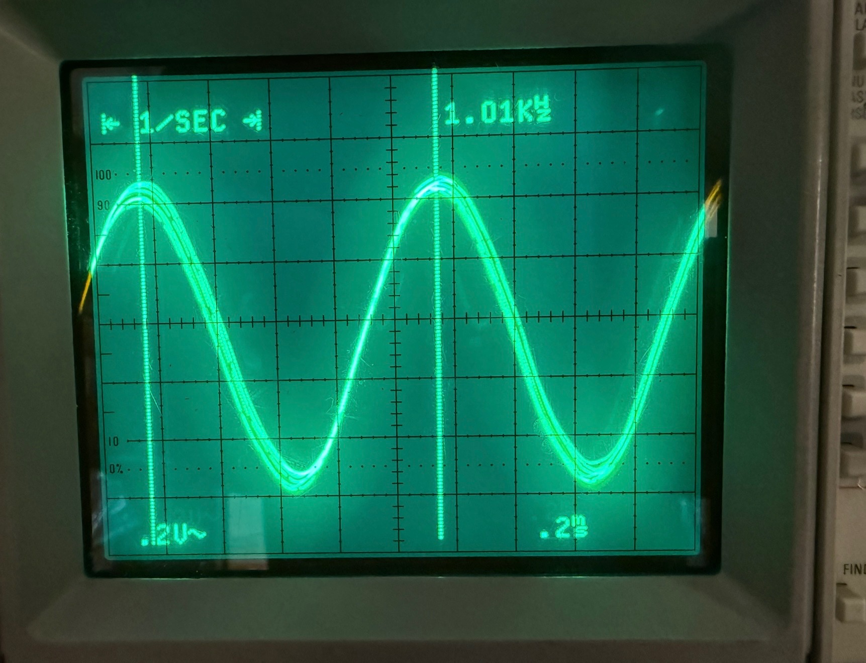
I'm assuming the coils are OK since I can receive so I guess the IFs are OK. I did an alignment following the instructions in the 146B service bulletin and the very clean waveform out of my signal generator is pretty distorted by the time it gets to the plate of the 42 tube. 
Noise on the plate of the output tube with volume at minimum and no signal applied:
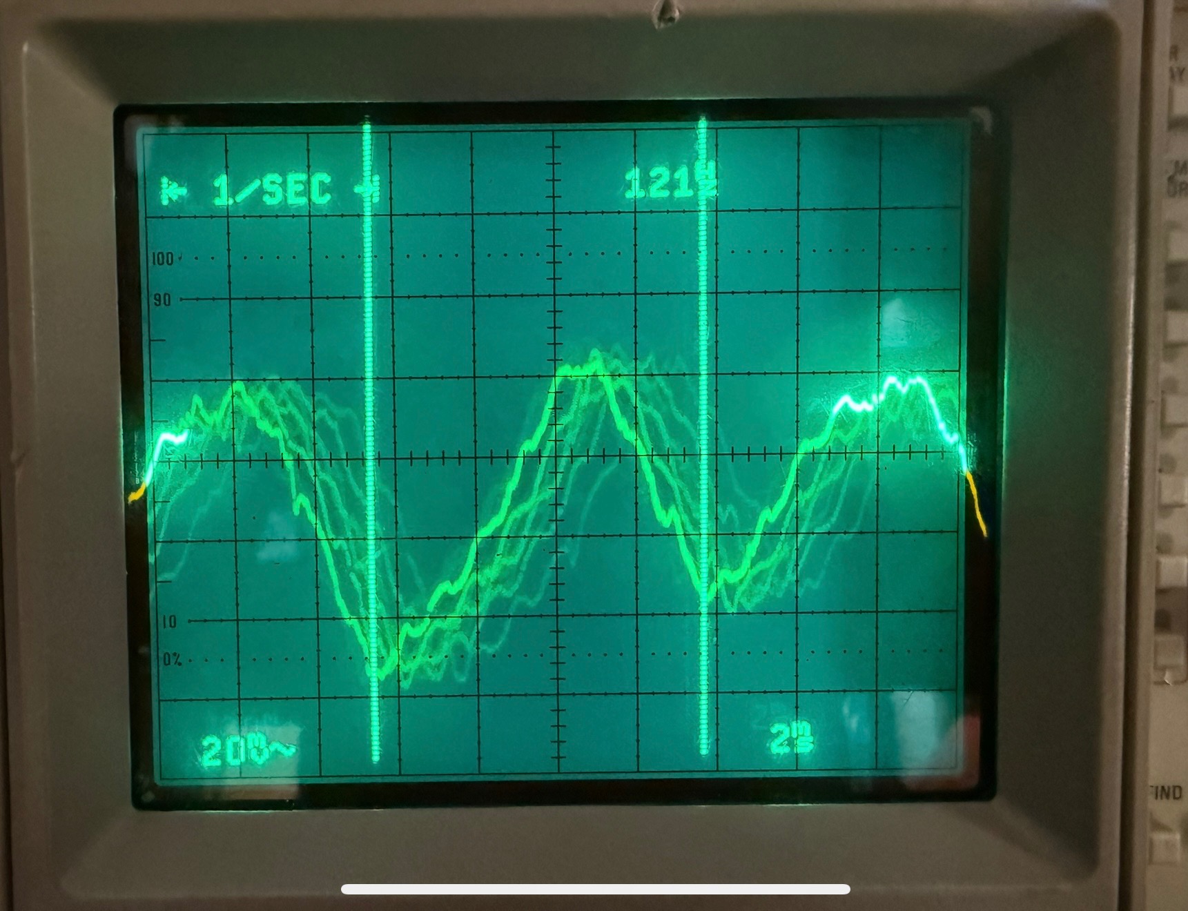
Plate of the 42 tuned in to 1500KHZ:
Close up:
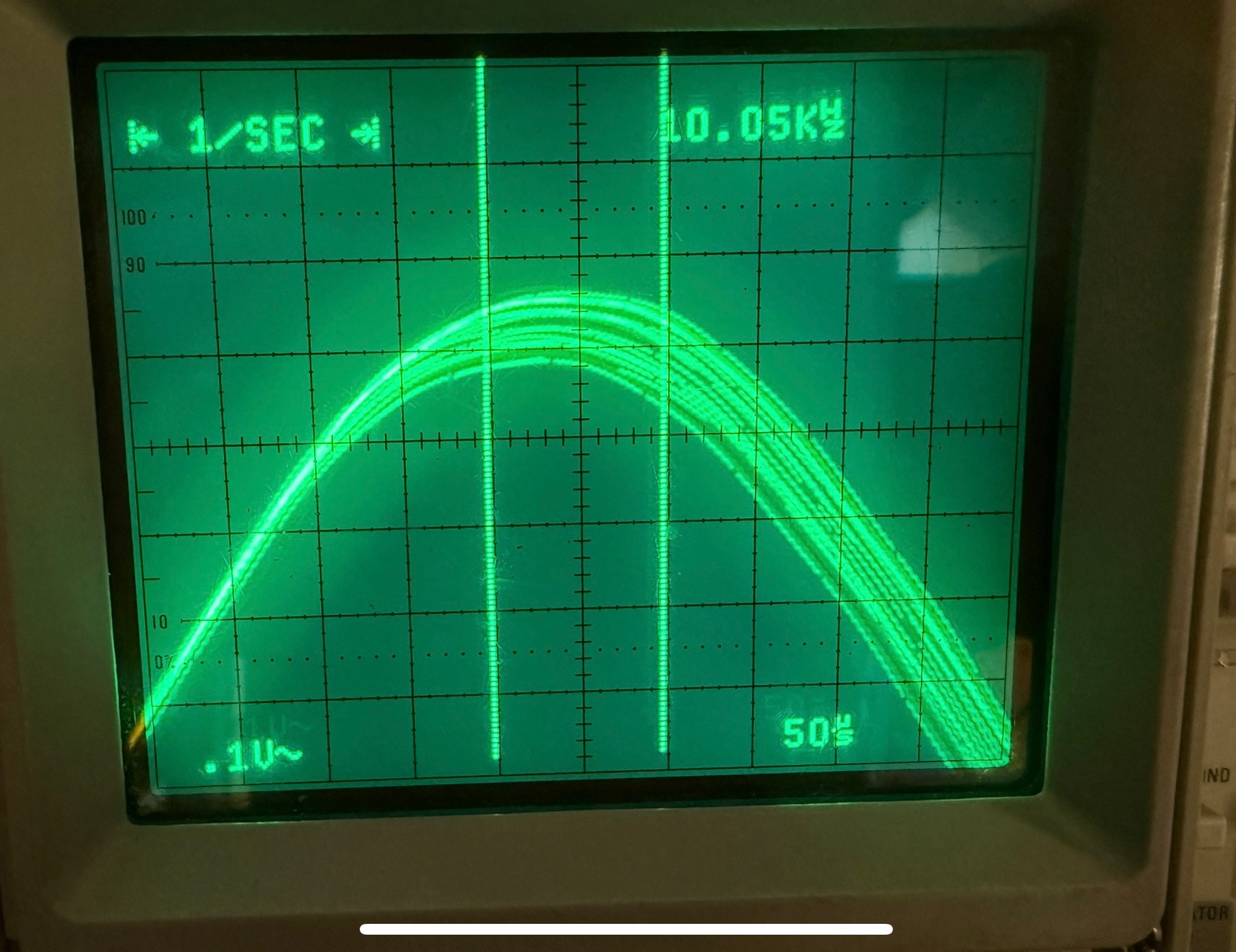
Do these waveforms look like anything in particular?
Thanks!
(This post was last modified: 02-04-2026, 05:02 PM by Kurt P.)
Posts: 553
Threads: 89
Joined: Jun 2022
City: Marion
State, Province, Country: NY
I'm not sure about the wave forms but if the noise you refer to is static then that might be noise from switching power supplies in your house or LED lights. I use a ground rod driven in the ground and connect that with a wire to the ground clip of the radio and that usually cleans up the static. Don't use house ground that will likely make things worse. My 89s use 8uF caps. It could be one of the coils is arching.
For a speaker plug you could use molex connectors. I don't bother with that. When I am satisfied with the radio I just put it back in the cabinet and call it done. Work out the problems while it is out of the cabinet.
Posts: 18,427
Threads: 622
Joined: Oct 2011
City: Jackson
State, Province, Country: NJ
Depending on how much you want to spend, either buy any curcular connector (Amphenol etc) rated at 400V or so, or use an old bad rectifier tube's base and the matching socket to make a plug.
People who do not drink, do not smoke, do not eat red meat will one day feel really stupid lying there and dying from nothing.
Posts: 2,327
Threads: 23
Joined: Jul 2020
City: Greenlawn
State, Province, Country: NY
100mV on a 250V output tube plate is not bad.
Many sets of this vintage us rather small capacitors. However, this set has a choke before the output stage, which provides sufficient filtering that a large cap is not needed.
I agree with Morzh that the home environment is full of noise and also recommend to NOT use the electrical system as a ground Since the ground wire runs i the same jacket as the other 2 conductors in Type NM cable, the noise can be coupled to the ground by induction. A water pipe is better, but the electrical system is grounded to it. A separate ground wire into good wet sandy soil is a very good ground. There are all sorts of ways to lower the resistance of a ground by adding certain salts.
As to connections to the speaker, you can solder a Molex pin to each connection on the output transformer terminal board and crimp or solder the mate to that pin onto the cable. Use 2 pin pairs of one size for the output transformer plate and B+ connections, with a male on one terminal and a female on the other terminal of the transformer primary. For the field coil to rectifier terminal, use a different size. This will prevent confusion by making it so only one way for the connection to be made (the right one) and one pin pair of another size. Therei s a hood that covers these terminals. Make sure that the insulation is still on the inside of the hood.
"Do Justly, love Mercy and walk humbly with your God"- Micah 6:8
"Let us begin to do good"- St. Francis
Best Regards,
MrFixr55
Posts: 20
Threads: 3
Joined: Aug 2024
City: Orange
State, Province, Country: CA
Quote:if the noise you refer to is static then that might be noise from switching power supplies in your house or LED lights.
Well, I went back and took another look and sure enough there was one piece of equipment that was creating most of the noise. I must have missed it the first time, unplugging it knocked down the noise a LOT! I can live with what's left. Even though I knew to check for this, I guess I just needed a reminder...
Quote:Depending on how much you want to spend, either buy any curcular connector (Amphenol etc) rated at 400V or so, or use an old bad rectifier tube's base and the matching socket to make a plug.
This is the way I'm going to go, good suggestion and thank you!
Kurt.
Users browsing this thread: 1 Guest(s)
|
|
Recent Posts
|
|
Philco P45-6365 Universal Transformer Instruction Manual
|
| Can anyone guide me to where this may be found?GRG — 03:00 PM |
|
54C Complete Teardown/Rebuild
|
| I don't think that I have encountered a 12Z3 before, curious how it uses one of those but includes a #43, which is a 25 ...Arran — 02:17 PM |
|
HiFi (Chifi) tube amp build - but my own design.
|
| It's the other forum. I'm also in DIY, but mostly read there. Honestly, I kinda jumped into this without much thought to...TV MAN — 10:43 AM |
|
Philco 71 Code 125
|
| Hello,
I am in need of a schematic for this radio. Mine has the three separate circular tube shields and a shadow me...dconant — 08:06 AM |
|
Stromberg Carlson 1500 Squeal
|
| And life just keeps getting more complicated.dconant — 07:57 AM |
|
54C Complete Teardown/Rebuild
|
| Hello Roy,
here is this one
sincerely Richardradiorich — 12:45 AM |
|
54C Complete Teardown/Rebuild
|
| Richard,
Had grabbed it already but thank you just the same. I find myself wanting to find some way to block out the...glyphmon — 12:03 AM |
|
54C Complete Teardown/Rebuild
|
| Hello roy,
here is a link to the schematic .
Sincerely Richardradiorich — 11:54 PM |
|
54C Complete Teardown/Rebuild
|
| Richard,
The Silvertone 2014 also is a transformerless set, so I am incorporating a 1:1 600 ohm audio isolation transfo...glyphmon — 11:37 PM |
|
Preliminary work on wife's Silvertone 2014
|
| Did an alignment today which was interesting. IF alignment went great, almost all was already spot-on. Adjusting on th...glyphmon — 11:35 PM |
|
Who's Online
|
There are currently 2656 online users. [Complete List]
» 2 Member(s) | 2654 Guest(s)
|
|
|

|
 
|









