Posts: 24
Threads: 3
Joined: Nov 2017
City: Bloomington
State, Province, Country: Indiana
Hello everyone, I’ve been working on a philco push button model 39-7. I’ve replaced all caps, checked resistors, and replaced all tubes. This set had been worked on before I got it. I get absolutely no sound. After replacing all parts mentioned above I got a motor boating sound for about 5 minutes, then that quit. All tubes light up except pilot light. I know the right push button controls dial tuning, but a I have no wires going to that button. I can’t figure out the schematic. I’ve seen videos on this radio and have seen two wire going to that push button. And as you can see from pics someone had done some soldering. Any idas would be greatly appreciated. Thanks
Jeff Lepore[attachment=34168][attachment=34169][attachment=34170]
Posts: 18,427
Threads: 622
Joined: Oct 2011
City: Jackson
State, Province, Country: NJ
Gosh, this thing is dirty and the rubber insulation is all cracked.
And what is that rope? Doesn't look like the dial cord.
https://www.nostalgiaair.org/pdfs/Philco...p-39-7.pdf
This sch?
There should be wires shown by the dash lines, one goes to the antenna xfmr, the otehr to the oscillator coil #6 or the cap 6A (in parallel to the coil).
People who do not drink, do not smoke, do not eat red meat will one day feel really stupid lying there and dying from nothing.
Posts: 2,327
Threads: 23
Joined: Jul 2020
City: Greenlawn
State, Province, Country: NY
The schematic is a little funky. In your set, the solid drawn C3A and B does not exist, the dotted line one does. The push buttons determine whether a push button capacitor channel is in use or if the tubing cap is in use. One of those push buttons will connect the tuning cap. Clean the switch, and ensure that the tuning cap is connected to the switchgear, that the switchgear is connected to the tuning cap and with the correct button pushed, the RF stator is connected to the grid cap of the 6A7 and to the antenna coil secondary, while the oscillator section stator is connected to the Oscillator coil.
Hope this helps.
"Do Justly, love Mercy and walk humbly with your God"- Micah 6:8
"Let us begin to do good"- St. Francis
Best Regards,
MrFixr55
Posts: 24
Threads: 3
Joined: Nov 2017
City: Bloomington
State, Province, Country: Indiana
Thanks for the suggestions, but everything I've tried, nothing works. I can't even get static. Something is dead. Might be for the dumpster.
Posts: 711
Threads: 46
Joined: Sep 2009
City: Lapeer, MI
State, Province, Country: USA
Jeff, After replacing the caps, resistors, and tubes you’re going to give up? I’d replace the crumbling wire next (could be a short or an open circuit), carefully clean the grid cap connections to insure proper contact, and figure out the twine that Morzh pointed out. Maybe post a couple of photos of the underside would be good. Keep talking to us! 
Joe
Courage will follow when Faith takes the lead.
Posts: 18,427
Threads: 622
Joined: Oct 2011
City: Jackson
State, Province, Country: NJ
I restored a 39-6 which is the same radio without pushbuttons. A simple animal.
So.
First things first.
1. Make sure your speaker's good. Disconnect one voice coil lead from the output transformer, make sure the voice coil has continuity.
Then check the Field coil. Right in-circuit, 1700 Ohm. Last, check the transformer's primary. 850 ohm, in-circuit. No problem with some plus-minus, as long as it is not a shor or open, or tens of Kiloohms instead of hunderds of Ohms etc.
OK, OK, I know, you had motorboating before, but Gosh knows, you coulda killed it. Due diligence.
2. Clean the darn thing. You don't know if the dirt is playing tricks on you. Tube sockets, especisally. Take out the tuning cap, at least blow it with some compressed air. All cracked wires - replace.
3. Check the tubes, not just for emission. yea, I know you replaced them. But still...
4. Every single resistor, see if you forgot any.
5. All magnetics: continuity. Every coil of every RF transformer.
6. Check the voltages.
7. Touch the 1st audio grid, see if it hums. Also check your volume pot.
We'll stop at this.
You should have your audio working before anything else.
People who do not drink, do not smoke, do not eat red meat will one day feel really stupid lying there and dying from nothing.
Posts: 2,327
Threads: 23
Joined: Jul 2020
City: Greenlawn
State, Province, Country: NY
Hi Jeff, don't give up; it is always darkest before dawn! +1 on what Morzh said.
Divide and conquer!
Touch the grid cap of the Audio tube (75). You should get hum. If no joy, verify the power supply, then attack per Morzh's instructions.
If the audio is good, touch the grid cap of the IF tube. You should get noise. If you ran a wire from the grid cap of this tube to the grid cap of another AC radio, you should get a lot of noise when attempting to tune the other radio, possibly actually stations, not clear, as I did not instruct you to connect the chassis together (This may be dangerous if the RFI caps (Death Caps) are leaking or one set is AC-DC).
If this test passes, then your issue is in the Convertor (1st Detector) stage. You previously stated that you have traced the circuit to the pushbutton switch that is supposed to connect the tuning cap to circuit and the cables appear to be missing. You can temporarily mod the radio to a 39-6, eliminating the pushbuttons. Check your wiring. Someone may have actually tried to do so but did it incorrectly.
Hope this helps.
Keep us all posted; we really want success for you!
"Do Justly, love Mercy and walk humbly with your God"- Micah 6:8
"Let us begin to do good"- St. Francis
Best Regards,
MrFixr55
Posts: 24
Threads: 3
Joined: Nov 2017
City: Bloomington
State, Province, Country: Indiana
Thanks for all the advice. I tried all that you suggested, but still no sound. I inherIted this radio and realized quickly it had been modified. Like the dial string is some kind of rope. it works but is tacky. And they’re globs of solder at many connections. I strongly think the problem has to do with the push button to control the tuner. Missing wires to push button. I looked at the 39-6 schematIc. It’s the same as mine. I would like to bypass the buttons, but have no clue how to do that. I’ve restored the cabinet, but I would really like this thing to work. I don’t give up, just frustrated. Next step will be to rewire all the cracked wire. That will be fun…. Thanks again. I’ll keep you posted.
Posts: 18,427
Threads: 622
Joined: Oct 2011
City: Jackson
State, Province, Country: NJ
So when you touch the grid of the 1st audio (cap of 75 tube), no hum?
And if you touch pin 4 pf the 41 tube, also no bum?
Please be specific in what "I tried what you suggested, but still no sound".
Because if this is the case, it should be fairly easy to see why there is no sound.
People who do not drink, do not smoke, do not eat red meat will one day feel really stupid lying there and dying from nothing.
Posts: 24
Threads: 3
Joined: Nov 2017
City: Bloomington
State, Province, Country: Indiana
I get no hum from 75 or 41. I get 2 ohms on voice coil with set on and off
Posts: 18,427
Threads: 622
Joined: Oct 2011
City: Jackson
State, Province, Country: NJ
>> I get 2 ohms on voice coil with set on and off
???
Please explain, not sure what "measuring ohms with set on" is.
Now, your output is not working.
When we ask you to test the speaker, did you test it and how?
Do the output tubes have proper voltages on them?
People who do not drink, do not smoke, do not eat red meat will one day feel really stupid lying there and dying from nothing.
Posts: 2,327
Threads: 23
Joined: Jul 2020
City: Greenlawn
State, Province, Country: NY
Hi Jeff,
OK, by touching the grid of the 75, you received no hum. This is bad but is good. At this porint, you work "backwards" starting at the speaker, power supply, etc.
The next instructions that I give may be very basic. Please forgive me if your skills are more advanced than my instructions. In all things, please exercise caution to prevent burns and dangerous electrical shock. All numbers referred to are from the schematic. Use either the schematic on the Phorum or the one from Nostalgia Air. Note that generally, the term "cap" is shorthand for capacitor unless referring to the "grid cap" on the top of some of the tubes. "Pinouts" for the rectifier and output tube are attached. The view is from the underside of the chassis. For the 41 tube, Pins 1 and 6 are larger in diameter than the other pins.
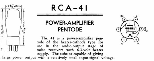
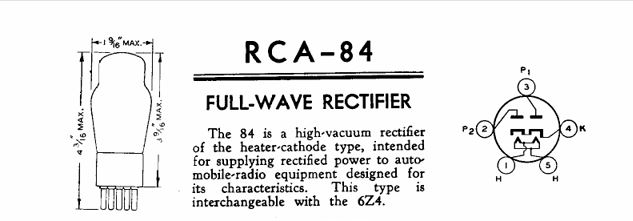
The following issues will cause no audio. Ensure that the set is unplugged. Verify resistance readings to determine: - Open speaker voice coil (must be checked while speaker is disconnected from the output transformer).
- Open speaker field coil. Measure with speaker connected, between + terminals of Caps #25 and 26.
- Open output transformer primary or wiring. Measure between Pins 2 and 3 of the 41 output tube for this resistance reading.
- Open resistors #23 or #24
- Open ground path between cathode of 41 output tube (pin 5) and chassis ground.
- Perform a good physical inspection of the power and audio sections of the radio. ensure that the field coil, output transformer primary and secondary are connected. Ohm the speaker voice coil. This must be done with at least one lead of the output transformer secondary disconnected from the speaker! In addition, note on the schematic, that one end of the secondary of the output transformer is grounded to the chassis, and that the other end of the secondary connects to the cathode terminal of the output tube, completing the circuit between the output tube cathode and B- (Chassis ground). If these 2 connections are not made, there will be NO AUDIO. If someone connected the cathode of the output tube directly to chassis, this would work also but would eliminate the feedback path provided to increase fidelity.
Perform the following tests very carefully as you are exposed to dangerous or fatal voltages. Do not proceed if not comfortable or familiar with safely making voltage measurements on live line powered equipment:
- With the set powered up and speaker connected, and with the meter set for DC volts at a range of 250V or higher, measure across the 12uF electrolytic cap #26. Note that this cap does NOT connect to chassis ground. The voltage should be 215VDC. If higher, don't worry for now. If low or Zero volts then there is an issue with the rectifier or the transformer. If no voltage at cap #26, switch the meter to AC 750V and measure between each plate of the rectifier tube and the center tap of the transformer (the negative lead of #26). between each plate and the center tap, there should be somewhere about 250-350VAC or so. The voltage from plate to plate will be somewhere between 400 and 800V. Measure this very carefully, preferably by sing clips instead of holding the probes as this is a dangerous voltage. If zero volts, then the transformer or its wiring is bad.
- If the voltage across cap #26 is good, then, with the DVM set for 250VDC or 600VDC measure across cap #25, the 4uF electrolytic cap. Note that the negative lead of this cap DOES connect to chassis ground. The voltage will be somewhat lower than the voltage across cap #26, in the 140-180V range. If very low or Zero volts, check between the negative lead of cap #26 and the positive lead of cap #25. If no voltage, the speaker voice coil or wiring is at fault. If the voltage s good, then resistors 23 and 24 are suspect.
- If the voltage across cap #25 is good, measure DC voltages between Pin 2 and Pin 5 of the 41 output tube. If low or Zero volts, then Resistors #23 and 24 or wiring between pin 6 and the output transformer secondary and wiring between output transformer secondary and ground is suspect.
I feel rather strongly that your main problem will be found following the above steps. This will restore function of the audio section and will pass the "hum test" (touching the grid cap of the 75 detector / 1st audio tube with the volume control set high or the grid cap disconnected).
There may be other issues. Please DO keep us posted; we are very happy to help you to successful completion of this project!!
OK, gang, gotta go and prepare gfor the upcoming blizzard!!
"Do Justly, love Mercy and walk humbly with your God"- Micah 6:8
"Let us begin to do good"- St. Francis
Best Regards,
MrFixr55
Posts: 24
Threads: 3
Joined: Nov 2017
City: Bloomington
State, Province, Country: Indiana
Before I try these instructions. Quick question: I have Cap #26 connected to ground. Where should it be connected? Previous owner removed the 12 mfd cardboard between the top of chassis and underneath. So old cap was grounded. so that’s where I grounded the new ones. Obviously that was wrong. I have grounded cap 25 to ground and also cap 26.
Posts: 1,797
Threads: 55
Joined: Feb 2015
City: Roseville, MN
Hi Jeff - I highly recommend that you not power up the radio until cap 26 is rewired. As MrFixr stated cap 26 is not supposed to be grounded. The schematic shows the center tap of the power transformer connected to resistor 24 as the point where the negative of cap 26 should be connected. This is probably a terminal near resistor 24. This terminal should measure about 300 ohms to chassis ground.
Posts: 18,427
Threads: 622
Joined: Oct 2011
City: Jackson
State, Province, Country: NJ
While I doubt #26 connected to GND would silence the radio all by itself, it is wrong and should be fixed.
Now the question, what the centertap of the Hi-V transformer is connected to?
People who do not drink, do not smoke, do not eat red meat will one day feel really stupid lying there and dying from nothing.
Users browsing this thread: 1 Guest(s)
|
|
Recent Posts
|
|
under chassis parts locator diagram for 1938 Zenith 9s262
|
| Has anyone gone to the trouble of creating an under chassis parts locator image? Yes, I can identify components by foll...bobloney — 08:57 PM |
|
Plug Voltages Needed For A 1943 CRV-20130 Power Supply
|
| Try looking at this site the book mark is for a old generator that I was given. David https://radionerds.com/index.ph...David — 08:36 PM |
|
Plug Voltages Needed For A 1943 CRV-20130 Power Supply
|
| Hello Everyone,
I am looking for voltage identification for all the pin positions on the socket of a CRV-20130 power su...Tonym4704 — 08:16 PM |
|
Philco P45-6365 Universal Transformer Instruction Manual
|
| Can anyone guide me to where this may be found?GRG — 03:00 PM |
|
54C Complete Teardown/Rebuild
|
| I don't think that I have encountered a 12Z3 before, curious how it uses one of those but includes a #43, which is a 25 ...Arran — 02:17 PM |
|
HiFi (Chifi) tube amp build - but my own design.
|
| It's the other forum. I'm also in DIY, but mostly read there. Honestly, I kinda jumped into this without much thought to...TV MAN — 10:43 AM |
|
Philco 71 Code 125
|
| Hello,
I am in need of a schematic for this radio. Mine has the three separate circular tube shields and a shadow me...dconant — 08:06 AM |
|
Stromberg Carlson 1500 Squeal
|
| And life just keeps getting more complicated.dconant — 07:57 AM |
|
54C Complete Teardown/Rebuild
|
| Hello Roy,
here is this one
sincerely Richardradiorich — 12:45 AM |
|
54C Complete Teardown/Rebuild
|
| Richard,
Had grabbed it already but thank you just the same. I find myself wanting to find some way to block out the...glyphmon — 12:03 AM |
|
Who's Online
|
There are currently 2034 online users. [Complete List]
» 1 Member(s) | 2033 Guest(s)
|
|
|

|
 
|









