Posts: 5,584
Threads: 291
Joined: Nov 2012
City: Wilsonville
State, Province, Country: OR
I've started to take a look at my C661 chassis.
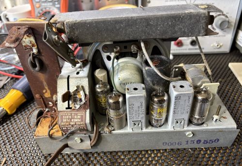
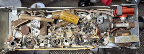
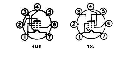
My first realization was that tube line up was not quite what was in the schematic. It puzzled me for a bit because I had not actually looked closely at the tubes, just took them out and started measuring resistors and transformers. When I got to the area around the 1U5 tube, the chassis wiring was different than the SCHEMATIC. A closer look at the tubes and Philco decided to wire the set with a 1S5 tube instead of the 1U5.
Another interesting item is that apparently Philco originally had a flashlight bulb in the side of the cabinet with a switch. You can just see it in the photo image on the schematic sheet. The set I have does not have that bulb. Probably realized that people would leave the light on and run the battery down pretty regularly. More later...
Posts: 5,584
Threads: 291
Joined: Nov 2012
City: Wilsonville
State, Province, Country: OR
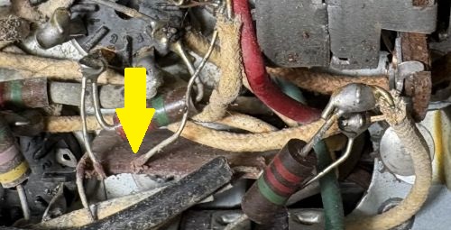
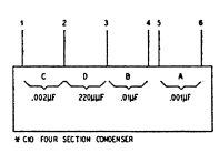
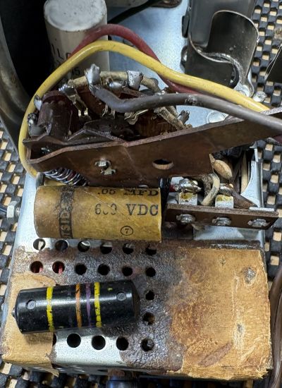
Here's something I have not run across before, probably because most of my restorations have been pre-1950. Its a four section wafer type condenser. I suspect its something I should replace with four new caps but its going to be a tight fit. Its the brown wafer that the yellow arrow is pointing to. Its C10 A, B, C, and D in the schematic.
Posts: 5,584
Threads: 291
Joined: Nov 2012
City: Wilsonville
State, Province, Country: OR
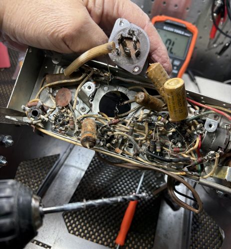
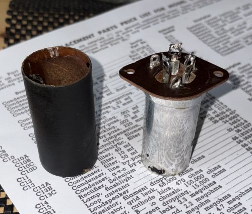
After checking resistors and transformers, I usually start by replacing the filter caps and on this set its a multisection capacitor can, C13, with 54/40/10 uF using twist tabs to lock the can into the mounting. In some sets I've cut the can off while it is still attached to the chassis thus eliminating resoldering at least some of the connections on the underside. Unfortunately I did not see an easy way to cut the can off; it was tucked in between the 1st IF, the tuning cap and the speaker. I suppose I could have taken the speaker off and in the end that might have been the better way to go but I decided to dismount the can after disconnecting everything that was attached to it. Unfortunately access to the underside C13 was difficult owing to multiple paper caps and resistors in the way. There were something like 10 or 11 wires, caps and resistors connected to the can leads and/or twist tabs. I took notes and they all match the schematic so I should be OK for reassembly. I attempted to simply untwist the tabs for the can removal but two of them had enough solder still on them that it was proving hard to slide the tabs out of the mounting wafer. After numerous attemps to desolder, ultimately I drilled out the rivets on the mount. The cardboard came off easily with a little heat (there was just a bit of tar at the top of the can holding it on.) I doubt I can get a rivit gun back in there for reattachment so a couple of machine screws and nuts will have to suffice.
Posts: 5,584
Threads: 291
Joined: Nov 2012
City: Wilsonville
State, Province, Country: OR
The caps have been replaced and remounted. I did not swap out the wafer cap C10 although that might have to happen in the future. I replaced the selenium rectifier with a 1N4007 diode and added 100 ohm 5 Watt resistor in series with R16 to give a total of 220 ohms after the diode. There was also one bumble bee style cap on the top side of the radio that I swapped out. Since it is visible I did put it inside a paper cap tube that I had although I did have to cut the length of the tube down a bit to get it to fit the space.
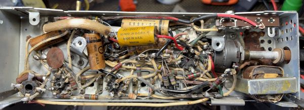
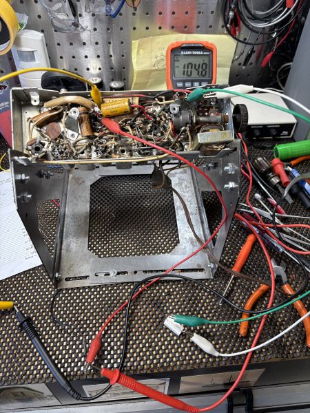
When I powered up the set I got good voltage readings at the point just after the added 100 ohm resistor (105vDC) and reasonably close readings at other points around the set. Unfortunately I was hearing absolutely nothing, not even static. After a bit of checking I realized I had put the audio output tube 3V4 in the wrong socket by mixing up with the 1U5(1S5) socket. After swapping them I was getting loud and clear stations.
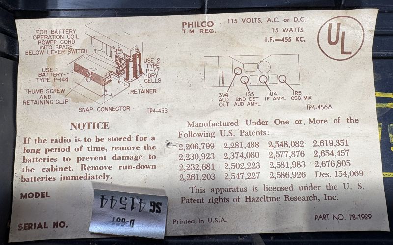
There is still some rust cleanup to do and I have to think about getting the battery connections cleaned up and useable as well. Its clear that the A battery leaked at some point. It uses two P77 batteries for the A voltage and a P144 for the B voltage. There is still some more cabinet work to do.
Here's the voltage check with the 100 ohm resistor still outside the chassis. I was planning on having to try a few different resistors but this one was fine the first time around.
Posts: 18,427
Threads: 622
Joined: Oct 2011
City: Jackson
State, Province, Country: NJ
Great job, Bob.
My Zenith I dealt with recently had the same thing, a selenium diode and a bumble bee cap.
Both had to go. I tend not not necessarily toss the seleniums, but this one was tired, and the output was plain low. It worked but not well.
People who do not drink, do not smoke, do not eat red meat will one day feel really stupid lying there and dying from nothing.
Posts: 3,186
Threads: 226
Joined: May 2008
City: Omak
State, Province, Country: WA
Hello Bob,
Great work on your chassis so far! I have the same set in my collection, also waiting to be restored. I’ve had to do the same as you—using machine screws to hold the capacitor can back in place. Some chassis are really tight, and that’s why I’ve held off on working on this particular set.
Sincerely Richard
Posts: 5,584
Threads: 291
Joined: Nov 2012
City: Wilsonville
State, Province, Country: OR
I worked on the battery connections a bit and applied the correct voltages (A battery @ 1.5v and B @ 75v) but nothing would come alive. There is a rotary switch mechanism that switches from AC to DC by inserting the plug in a sheet metal housing around the switch and this holds the lever arm in the DC position. There may be a problem with the connections in the rotary switch but I elected not to try to sort it out. The set is missing a retaining clip that holds the P-144 B battery in place and I want to put this in the swap meet next Saturday so I'll call it good enough.
Here's the inside all back together.
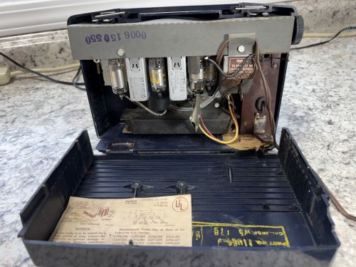
Here's a close up of the label on the inside and its just as I type this up that I realized the label identifies this set at a D661 which actually makes it a 1956 radio but then who's counting.
The thread on the cabinet is at this LINK.
Users browsing this thread: 1 Guest(s)
|
|
Recent Posts
|
|
Philco P45-6365 Universal Transformer Instruction Manual
|
| Can anyone guide me to where this may be found?GRG — 03:00 PM |
|
54C Complete Teardown/Rebuild
|
| I don't think that I have encountered a 12Z3 before, curious how it uses one of those but includes a #43, which is a 25 ...Arran — 02:17 PM |
|
HiFi (Chifi) tube amp build - but my own design.
|
| It's the other forum. I'm also in DIY, but mostly read there. Honestly, I kinda jumped into this without much thought to...TV MAN — 10:43 AM |
|
Philco 71 Code 125
|
| Hello,
I am in need of a schematic for this radio. Mine has the three separate circular tube shields and a shadow me...dconant — 08:06 AM |
|
Stromberg Carlson 1500 Squeal
|
| And life just keeps getting more complicated.dconant — 07:57 AM |
|
54C Complete Teardown/Rebuild
|
| Hello Roy,
here is this one
sincerely Richardradiorich — 12:45 AM |
|
54C Complete Teardown/Rebuild
|
| Richard,
Had grabbed it already but thank you just the same. I find myself wanting to find some way to block out the...glyphmon — 12:03 AM |
|
54C Complete Teardown/Rebuild
|
| Hello roy,
here is a link to the schematic .
Sincerely Richardradiorich — 11:54 PM |
|
54C Complete Teardown/Rebuild
|
| Richard,
The Silvertone 2014 also is a transformerless set, so I am incorporating a 1:1 600 ohm audio isolation transfo...glyphmon — 11:37 PM |
|
Preliminary work on wife's Silvertone 2014
|
| Did an alignment today which was interesting. IF alignment went great, almost all was already spot-on. Adjusting on th...glyphmon — 11:35 PM |
|
Who's Online
|
| There are currently no members online. |

|
 
|







