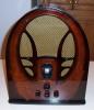
Hello Forum members. I would have posted this in earlier 37-640 posts that I made, but they have been closed so I am starting this new one on a wiring question I have run into. Need a little more help with 37-640. As I reassemble and reconnect chassis wires, I can not locate wire number 8 yellow on the Ron Ramirez drawing. The drawing shows it connects to pin 5 of the 6K7 IF amp tube but I can not determine where it connects from there. Tube data that I see shows that pin 5 is Grid 3. I do currently have a thin black insulated wire on pin 5 but it goes inside the bottom of the IF transformer. Is it possible that my run did not have another wire on pin number 5?
I did look at the 37-620 chassis that I have and there is only that one thin black insulated wire on pin 5 of the 6K7 IF tube as well.
Can anyone help. Thanks so much
That is not what the schematic indicates. 6K7 G3 is the Suppressor grid on pin 5 which is normally attached to the Cathode. In this case, according to the schematic, there is supposed to be a small negative bias from the power supply in addition to the AVC circuit. That grid is also connected to the other 6K7 rf Amp Suppressor grid. The only connections to an IF transformer for the 6K7 IF tube is the grid cap and the plate, pin 3.
So, is it possible that Ron Ramirez yellow wire from 6K7 pin 5 goes to the other 6K7 pin 5?
morzh, thanks for the replay but when I open that thread at the very last page it says the thread is closed.
RodB, I will look closer but in the meantime, I will attach a photo of what I see. It also appears that no other
wires were previously attched to pin 5. Also, I just fountService bulletin 253 for code 121. amoung the verbage, it says "The first IF Transformer, part No 32-2274 has a stabilizing winding which is placed in series with the suppressor grid of the 6K7 I.F. tube. The short or yellow colored lead is connected to the ground lug and the long lead to the suppressor grid."
It looks to me like the mention of the yellow wires are rplaced by the black thin insulated ones. There is a second one of the thin black insulated wires also going into the IF transformer and when I checked. it is connected to ground.(you maybe able to also see it in the attached photo) The reason it looks like there was solder work on that pin 5 is because insulation was flaking off the wire and so I Replaced the wire.
Hello Philco Forum members. I have run into question while reassmbling my 37-640. I have attached a photo of the rear of the chassis with the red arrow pointing to the screw and the flat metal slide sbove it coming out of the chassis top. Can someone tell me what this is and should the flat metal slide do something other than confuse me? Should the slide move up and down?
When I get this all put back together, I will explain all that I had to do to replace the broken bandswitch wafers in th rear of the RF unit and replace all the wires coming from the bandswitch. I still have to try to repair a broken wire in the IF transformer when I remember which transformer it is. I have never done that type of repair before so I will try to read up on it.
Thanks, John
That chassis screw is supposed to have a rubber chassis mount that sits in the hole and, along with two more in front, gives the rf chassis a little lift and adjustable positioning. If you do not have the rubber mounts installed, the dial will be shifted down.
Rod, thanks for the reply. Is this perhaps the rubber part that I already have from Renovated Radios that goes between the RF unit and the rear of the main chassis with a large washer?.
RodB, Yes I found that rubber grommit, istalled it and thanks to you, understand what it really does. It really does not seem apparent of what its for until you install the RF unit back in the main chassis. I am beginning to think this radio may work once its all back together!
Hello Philco members. I am in the process of checking the IF transformers on my 37-640. Since I have never worked on an IF transformer before, I have a couple of questions. I have attached a photo of the first one I have taken apart( it is the one with a grid cap wire). I see no broken wires and when I test with the ohm meter, the top coil reads 20.9 ohms and the bottom coil reads 11.6 ohms. Does that seem ok? If this is ok, I will reassemble and take apart the other IF transformer because it may be the one that I originally saw a broken wire some months ago when I first started working on this chassis. Thanks john
I'd say that IF is fine. Looks nice and clean. You might take a closer look at the trimmers for dirt and cracked mica wafer. Be careful around the wires, measure the coils again just before reinstalling.
This is where I would ... err on the side of caution.
While the mica caps and all might (and likely are) just fine, any inspection of them involving touching could result in problems.
So, my personal preference would be: "OK, I opened it, I saw it, now I will close it."
Except that I would never open it in the first place unless there were indications that the IF can needs attention.
People who do not drink, do not smoke, do not eat red meat will one day feel really stupid lying there and dying from nothing.
Thanks all for the reply. I put it back together but found it somewhat difficult lining up the adjustment scews with the holes in the top of the IF can. I then took the second one apart before reading your
warning replies about the danger in messing with them. The second one seems ok also because it read 86.4 ohms and 8.3 ohms It still had the original brown plastic type wrapper around the coils so I just measured the the terminal connections from the top of the transf so as not disturb anything else and I will reassmble it as well. At least I can say I know a little more about them, but in the future I will keep my paws off.
Happy Memorial Day Phorum members. I have finally goten my 37-640 back together. I put it on a my variac and slowly turned up the voltage whlle watching the elctronic watt meter set to the amps function. At 120 volts, my amp reading stayed at 0.06 which I think is ok. I connected up a 10 foot stranded 16 gauge wire for an antenna but could not get any reception. I think this is probably because I had done so much component replacement including replacing the antenna coil assembly, that an alighnment would probably help. In the allighnment instructions, going to step 1 where I set the radio dial at 550kc and set the sig gen at 470kc, I can hear the tone but it not not at 470. Can someone tell me what adjustments will bring me to the 470. Is it the ANT 1500kc, the RF 1500kc or the OSC 600kc or 1600kcthat are on the bottom of the chassis? Thanks as always, John