Fada 1000 Component Question
Posts: 109
Threads: 15
Joined: Mar 2024
City: BERTHOUD
State, Province, Country: CO
Craftsmanship is an ongoing cycle of learning fueled by patience, persistence, and care, where every project refines our judgment and challenges our skills, in the steady pursuit of the Path to Mastery.
Posts: 2,327
Threads: 23
Joined: Jul 2020
City: Greenlawn
State, Province, Country: NY
Hi SRv2,
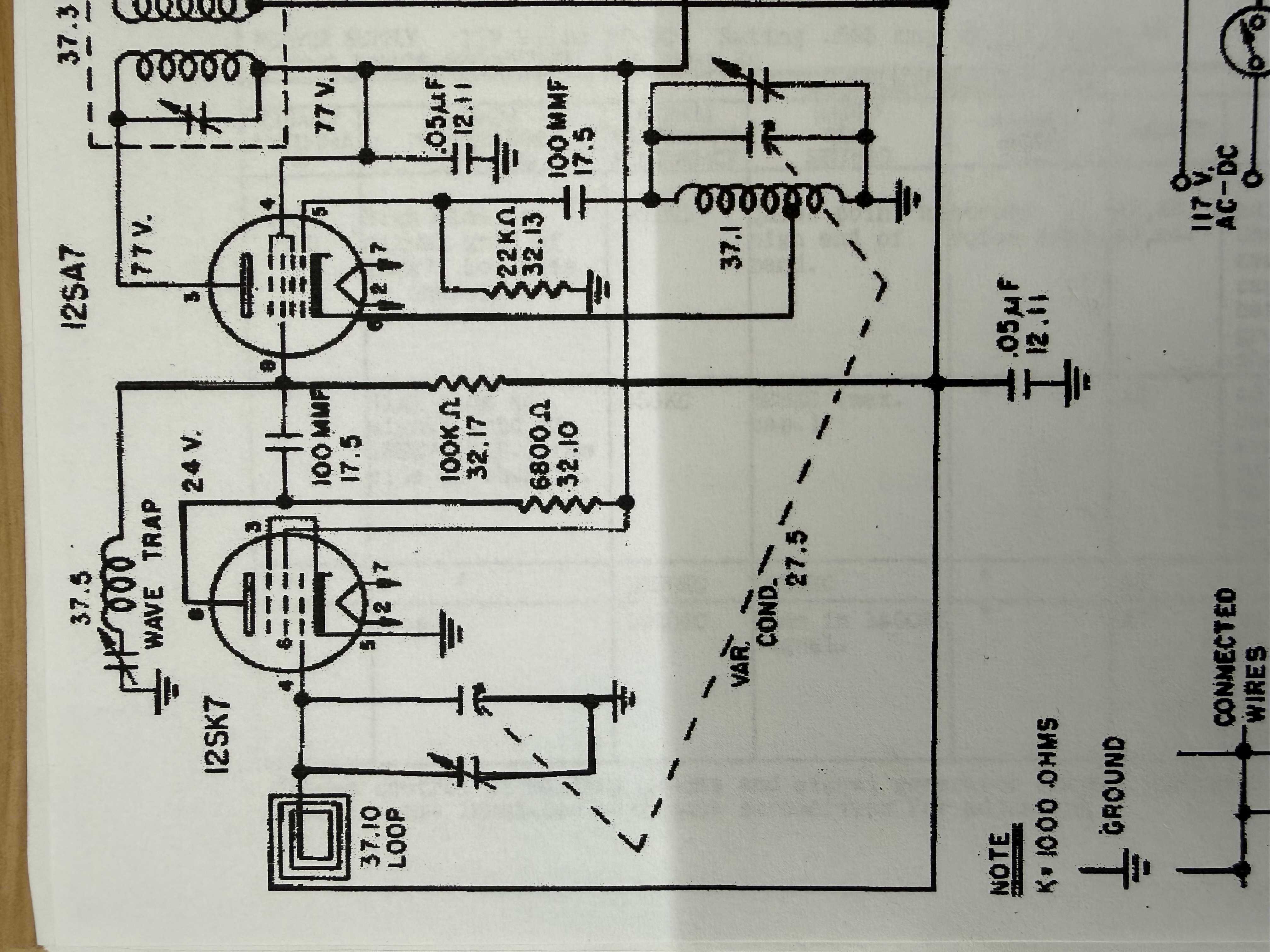
No, no one should throw shade your way. The wave trap is between the mixer grid and ground. One would think that there would be a tuned circuit consisting of a gang of the tuning cap and a n appropriate coil (such as the secondary of the RF to convertor transformer) at the mixer grid, but this is a budget radio (or was a budget radio; collectors pay a mint for this now).
This may be a condenser or a bad (open) coil, or a bad (open) resistor. Unfortunately, run changes don't always make the schematic. For now, leave it out and connect the condenser and loop directly to the grid of the RF amp and see what happens; nothing will smoke.
Not all radios had this wave trap. I have several radios made in New York. The borough of Queens housed several radio manufacturers including Emerson, Grebe, FADA, Andrea Aladdin and others. Others were made in New York City (Manhattan). RCAs were built in Camden, NJ. These wave traps were often needed in areas with a lot of ship traffic, especially in the Great Lakes area, a major ship transportation area (Iron Ore, Coal, grain, etc.), as ship to ship and ship to shore communications for navigation and RDF were often on the Long Wave band and in the 420 - 480 KHz range, where the IF frequency of many radios fall. The only radio that I have that has a wave trap is a Coronado (Gamble Skogmo) battery farm set, likely sold for farms near the Great Lakes. Radios were built for certain areas. For example, there were 4 tube superhets (no IF amp, only IF tuned circuits) for the city, 5 tube superhets (The AA5) for suburban areas and 6 tube sets (The AA5 circuit with an added tuned RF amp) for fringe areas. Your set may have been built for the Great Lakes area.
Hope this helps.
"Do Justly, love Mercy and walk humbly with your God"- Micah 6:8
"Let us begin to do good"- St. Francis
Best Regards,
MrFixr55
Posts: 109
Threads: 15
Joined: Mar 2024
City: BERTHOUD
State, Province, Country: CO
MrFixr,
This helps a lot. Mainly because it was not a wave trap, so my ego remains mostly intact. This unit has the wave trap on the schematic but it is nowhere to be found. There are multiple component changes around the RF amp circuit, I'm assuming like you said a run change that didn't make the schematic. This unit is from 1945, so I had gone through all my old Rider books before and after looking at Fada models trying to see if a schematic revision had been issued, no success. The other reason I questioned it was due to not-too-great performance whereas I had thought a 6 tube unit with an RF amp would have done so much better than an AA5. Like you said "budget radio". This is my first Fada, and I'm not very impressed. I would have saved myself some disappointment if I had just put it on a shelf in my home on display. After working on this thing, I lost a bit of luster for my first Catalin unit. Meanwhile I installed a jumper in place of this and aligned the radio best I can. It performs decently but the little Philco 49-500 I just finished has better sensitivity. NOW, I'll reassemble and put it on a shelf and stare at it. Thanks for the feedback!
George
Craftsmanship is an ongoing cycle of learning fueled by patience, persistence, and care, where every project refines our judgment and challenges our skills, in the steady pursuit of the Path to Mastery.
Posts: 5,654
Threads: 56
Joined: Sep 2008
City: Sandwick, BC, CA
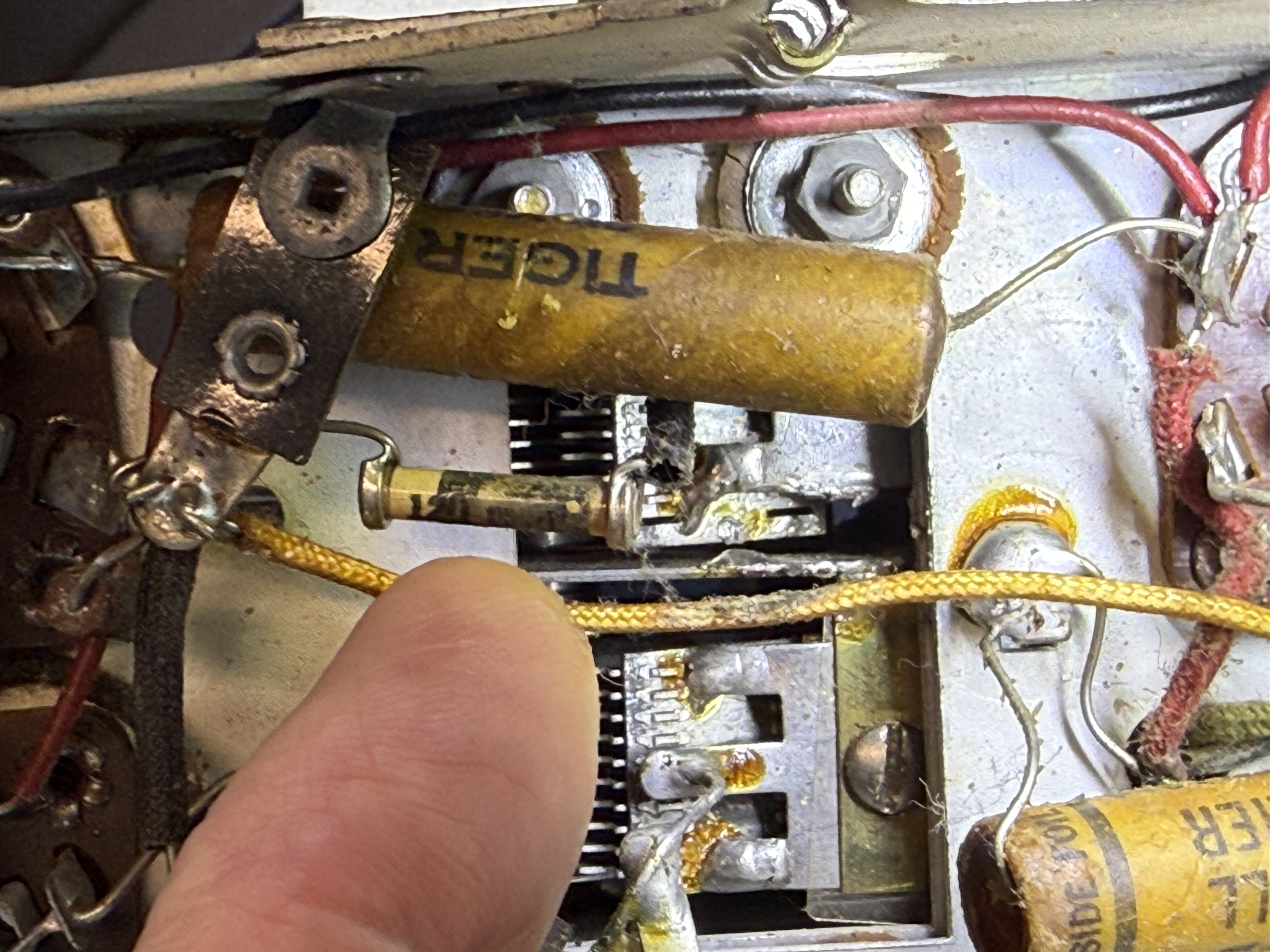
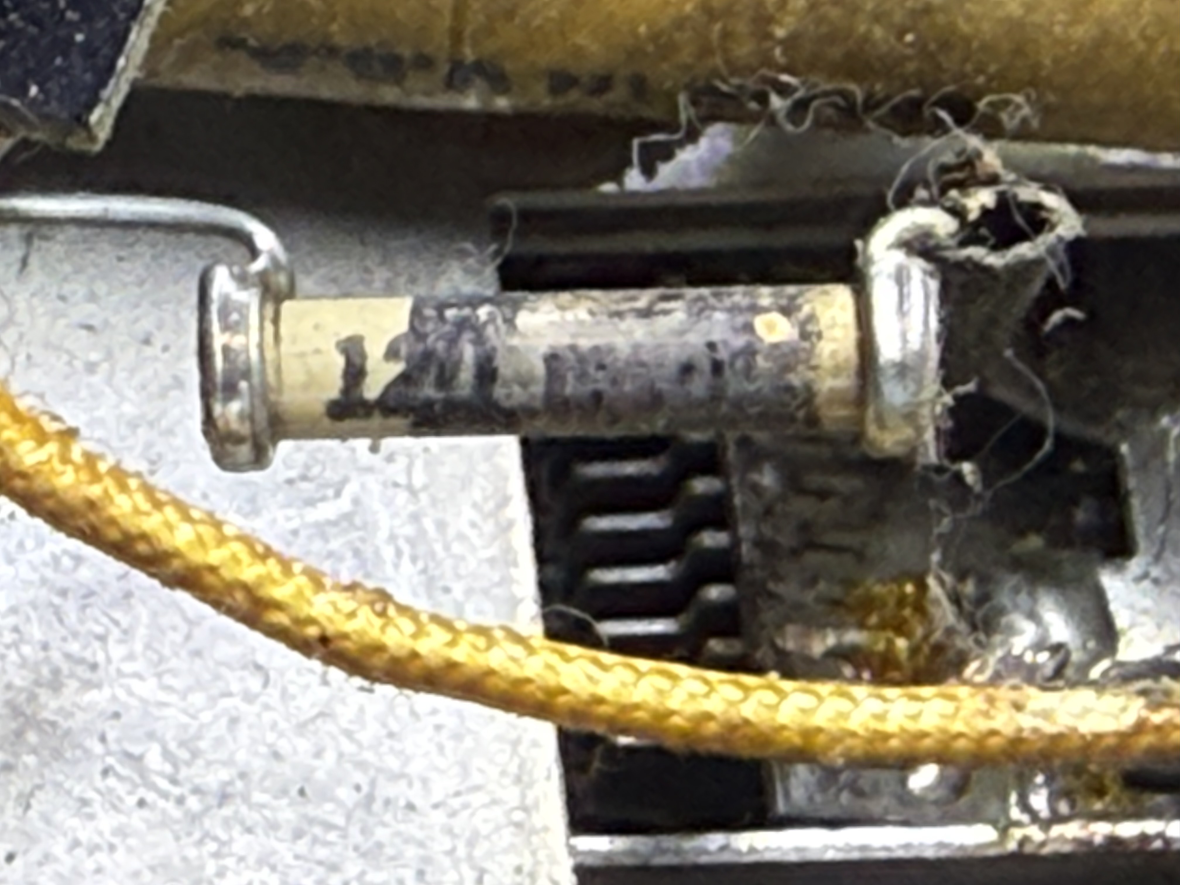
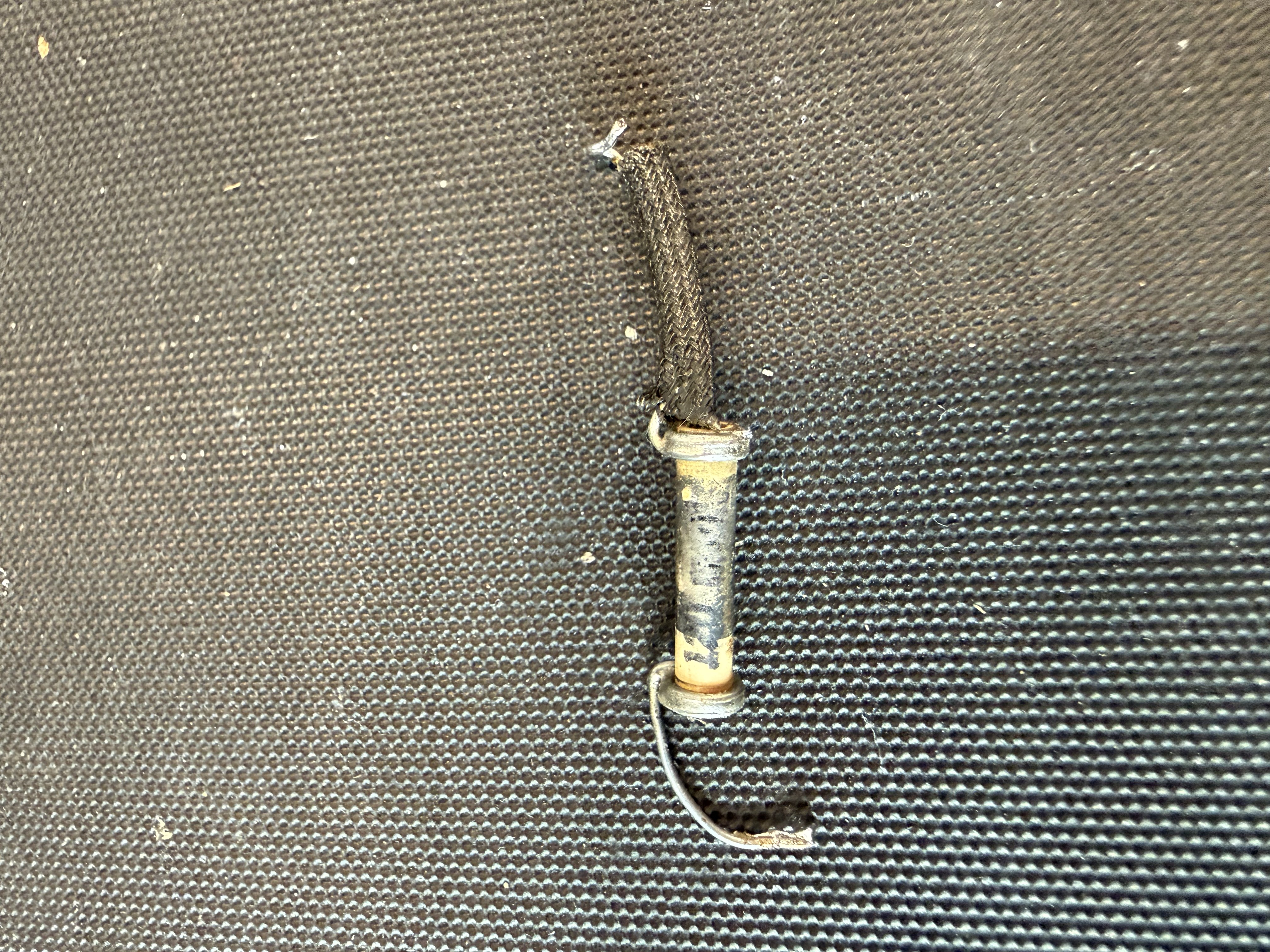
It's a small ceramic capacitor, even though it does look like a dogbone resistor. I'm not sure why it was used but maybe they concluded that there was a tracking problem at alignment and decided to slightly reduce the capacitance to the stator of the antenna section of the tuning condenser.
Regards
Arran
Posts: 18,427
Threads: 622
Joined: Oct 2011
City: Jackson
State, Province, Country: NJ
Take a C-meter to it, if it measure some hundreds of pFs and infinite resistance, it is a tubular ceramic cap.
I am a bit surprised as the grid then is floating, but then I see a wire going from the Grid where this cap comes to the #4 pin. Where does it go?
People who do not drink, do not smoke, do not eat red meat will one day feel really stupid lying there and dying from nothing.
Posts: 3,188
Threads: 226
Joined: May 2008
City: Omak
State, Province, Country: WA
Hello George,
I agree with Mike that looks like a tubular ceramic cap!
Sincerely Richard
Posts: 109
Threads: 15
Joined: Mar 2024
City: BERTHOUD
State, Province, Country: CO
I was able to dig out and get working my old Radio Shack multimeter that has capacitance and it reads 0.1 nf. I measured a bunch of other caps to ensure the meter was working. And to answer Mike's question, There is an added 1M ohm resistor from the grid pin 4 down to the other side of the antenna loop (parallel with the loop). These two components are not on the schematic. The radio functions well without this ceramic cap and a jumper in place of it. George
Craftsmanship is an ongoing cycle of learning fueled by patience, persistence, and care, where every project refines our judgment and challenges our skills, in the steady pursuit of the Path to Mastery.
Posts: 3,188
Threads: 226
Joined: May 2008
City: Omak
State, Province, Country: WA
Hello George,
I sure that part is some where on the schematic unless someone added it .
Sincerely Richard
Users browsing this thread: 1 Guest(s)
|
|
Recent Posts
|
|
Plug Voltages Needed For A 1943 CRV-20130 Power Supply
|
| That looks a lot like an aircraft connector of some kind, even if it's a U.S.N power supply. I have a book somewhere abo...Arran — 02:56 AM |
|
Plug Voltages Needed For A 1943 CRV-20130 Power Supply
|
| hello david,
I have a similar generator in my collection that features a cast iron, single-cylinder Briggs & Stratt...radiorich — 01:00 AM |
|
under chassis parts locator diagram for 1938 Zenith 9s262
|
| Has anyone gone to the trouble of creating an under chassis parts locator image? Yes, I can identify components by foll...bobloney — 08:57 PM |
|
Plug Voltages Needed For A 1943 CRV-20130 Power Supply
|
| Try looking at this site the book mark is for a old generator that I was given. David https://radionerds.com/index.ph...David — 08:36 PM |
|
Plug Voltages Needed For A 1943 CRV-20130 Power Supply
|
| Hello Everyone,
I am looking for voltage identification for all the pin positions on the socket of a CRV-20130 power su...Tonym4704 — 08:16 PM |
|
Philco P45-6365 Universal Transformer Instruction Manual
|
| Can anyone guide me to where this may be found?GRG — 03:00 PM |
|
54C Complete Teardown/Rebuild
|
| I don't think that I have encountered a 12Z3 before, curious how it uses one of those but includes a #43, which is a 25 ...Arran — 02:17 PM |
|
HiFi (Chifi) tube amp build - but my own design.
|
| It's the other forum. I'm also in DIY, but mostly read there. Honestly, I kinda jumped into this without much thought to...TV MAN — 10:43 AM |
|
Philco 71 Code 125
|
| Hello,
I am in need of a schematic for this radio. Mine has the three separate circular tube shields and a shadow me...dconant — 08:06 AM |
|
Stromberg Carlson 1500 Squeal
|
| And life just keeps getting more complicated.dconant — 07:57 AM |
|
Who's Online
|
| There are currently no members online. |

|
 
|