Posts: 5,584
Threads: 291
Joined: Nov 2012
City: Wilsonville
State, Province, Country: OR
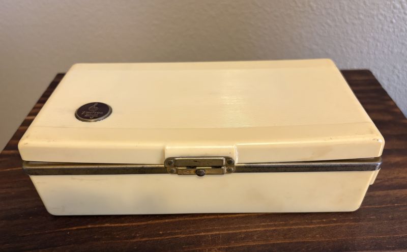
I've started looking at the Emerson 558 portable I recently acquired. Its got a relatively nice plaskon cabinet although the lid is slightly warped as many of this model are. From what I've read and seen online there is no good way to unwarp it. Heating can cause problems such as cracking and deformation so I'll leave it alone.
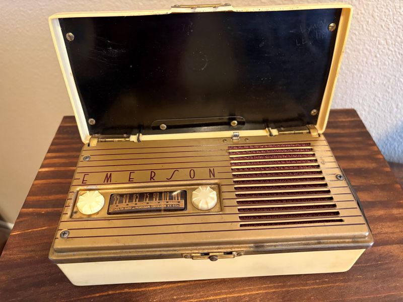
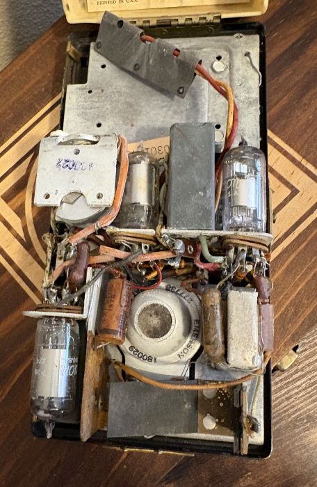
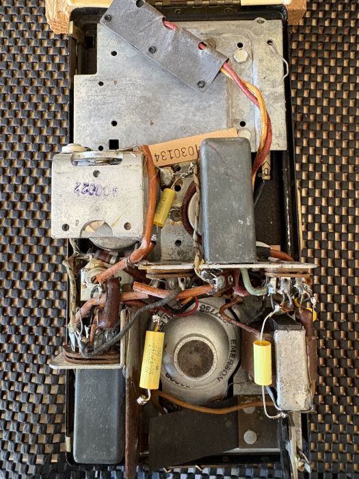
Inside the set, its jam packed. Most of the paper caps seem to be in places that I should be able to get them swapped out and there is an electrolytic cap that is also accessible. You can take the chassis completely out of the plastic cabinet but it requires some desoldering of the on/off switch activated by opening the lid and perhaps a few other things I haven't seen yet. I think I'll try to do the recap without removing it and only attempt it if I hit a roadblock.
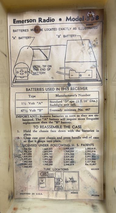
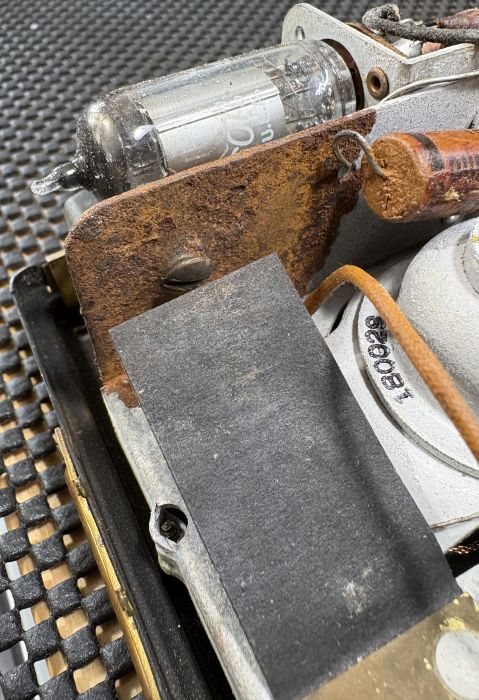
As long as all else is OK I think the main problem will be getting the "A" Batter holder back into reasonable shape. Its had a battery leak causing considerable corrosion to the point where the connection point for the negative end of the A battery was corroded away and someone put a small screw in its place.
In the category of "Things you find in your radios" a previous owner or owner's child has scratched two names into the antenna board on the inside of the lid of the radio. It says "Lynn" and "Leslie."
For those of you who want to follow along, here's the link to the schematic.
I don't quite know why there would be a 16uF electrolytic (C17 between the audio transformer primary and ground) in a battery set. I have a 22uF 160v cap I could put there, is the capacitance value critical in this situation? Its not smoothing AC like in a filter circuit. Any thoughts?
Should be fun...more later
Posts: 4,832
Threads: 437
Joined: Jun 2011
City: Boston
State, Province, Country: Massachusetts
Looks cramped in there, good luck .Paul
Tubetalk1
Posts: 2,327
Threads: 23
Joined: Jul 2020
City: Greenlawn
State, Province, Country: NY
I think that the cap is there to deal with varying internal resistance of the battery. I am not sure, but I can tell you from experience that if the cap is not there, there is motorboating, oscillation, noise, etc. The cap is (or should be) on the B+ side of the OPT, not the Plate side. Bias is provided by a resistor between the - terminal of the B Battery and chassis ground. At the junction of this resistor and the negative terminal of the B Battery is considered "C-". The grid leak resistor for the output tube connects to this point, providing the required grid bias. This is similar to many pre-WWII radios where the cathode of the Audio output (and usually all other amplifier tubes connects to chassis
I think that you can get away with the 22 uF 160WV cap. Since this is pure DC, there is no current draw after original charging of the cap upon turn-on.
"Do Justly, love Mercy and walk humbly with your God"- Micah 6:8
"Let us begin to do good"- St. Francis
Best Regards,
MrFixr55
Posts: 5,584
Threads: 291
Joined: Nov 2012
City: Wilsonville
State, Province, Country: OR
My though exactly Paul. I have been poking around trying to trace wires so I could become familar with the various parts. I've located all but one of the the paper caps so far. In addition to being small, if you leave the chassis in the cabinet it is more difficult to look at all sides of things with the bottom hinged portion still connected.
Posts: 5,584
Threads: 291
Joined: Nov 2012
City: Wilsonville
State, Province, Country: OR
Thx Mr.F, yes the cap is on the B+ side of the OPT not the plate side.
Posts: 5,654
Threads: 56
Joined: Sep 2008
City: Sandwick, BC, CA
My experience with battery sets is that if they included a small value electrolytic on the B+ line, then it needs to be there. I have encountered these in a number of farm battery sets over the years, usually in a wax sealed cardboard tube, dried up, and likely perished inside, and with it open circuit the set will hum, at least on a battery eliminator, it may actually be a low frequency oscillation. Also the value is not too critical, but I always used 150 vdc caps as replacements, that way I could use them in 1.5 volt and 90 volt sets as well as 2 volt and 135 volt ones.
Regards
Arran
Posts: 5,584
Threads: 291
Joined: Nov 2012
City: Wilsonville
State, Province, Country: OR
Thanks Arran. I'll be replacing the existing one.
Posts: 5,584
Threads: 291
Joined: Nov 2012
City: Wilsonville
State, Province, Country: OR
The recapping is done. Since the space was tight I elected not to stuff the old caps and also did some hanging wire connections rather than desoldering things at the tube pin lugs or other equally tight spots. I'm waiting for a TS5 tube to arrive, the old one was bad and I still need to deal with the A battery corroded connector plate. To get the electrolytic in, I did have to loosen those 3 screws on that hold the chassis into the cabinet and that gave enough space to work with out completely taking the chassis out. Time will tell if it will all work out OK.
Posts: 3,188
Threads: 226
Joined: May 2008
City: Omak
State, Province, Country: WA
Hello Bob,
That reminds me of how cramped my RCA BP-10 is; it has a very similar design.
Sincerely Richard
Posts: 18,427
Threads: 622
Joined: Oct 2011
City: Jackson
State, Province, Country: NJ
Well, this design not only cramped but also very...distributed in space.
Makes it even less convenient.
People who do not drink, do not smoke, do not eat red meat will one day feel really stupid lying there and dying from nothing.
Posts: 5,584
Threads: 291
Joined: Nov 2012
City: Wilsonville
State, Province, Country: OR
I’m sure it was a well choreographed assembly line such that each component got put in at the point where it was easiest.
Posts: 5,584
Threads: 291
Joined: Nov 2012
City: Wilsonville
State, Province, Country: OR
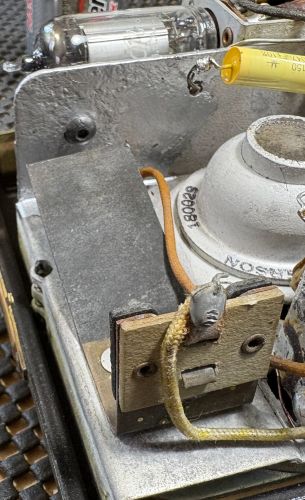
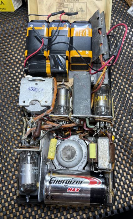
I reached the finish line for this radio. It was actually one of the easiest restorations I've done. The cabinet was in good shape to start with and there were only a few caps to replace. I never did find cap C11 so if its there it still should be replaced. The corroded part of the frame that served as the connection for the negative on the A Battery was stripped of loose rust with a small wire brush on a Dremel tool, coated with Rustoleum Rust Reformer(two coats of the liquid version) and painted with Rustoleum Aluminum (oil based) just to make it look a little better. The actual electrical contact was similar to the previous repair, a button head machine screw with a wire secured with a nut and washer soldered to ground. Its a bit of a tight fit for the A Battery but the case closes so all should be good. I'll finish by making a reproduction Eveready 467 battery box for the B battery.
[Video: https://youtu.be/wHj7SbJHbKY?si=RC2T2GuD75dM9J4X]
Posts: 18,427
Threads: 622
Joined: Oct 2011
City: Jackson
State, Province, Country: NJ
Great little Emerson.
Bob, BTW, a friend of mine needed to re-do the charge base for Rumba vacuum, and he found out they do sell those battery spring contacts after all. Maybe there are some that could be bought, that would fit radios.
People who do not drink, do not smoke, do not eat red meat will one day feel really stupid lying there and dying from nothing.
Posts: 5,584
Threads: 291
Joined: Nov 2012
City: Wilsonville
State, Province, Country: OR
I did consider taking one of those black plastic battery holders you can buy and using it or parts of it but ultimately decided this approach changed things the least.
Posts: 5,654
Threads: 56
Joined: Sep 2008
City: Sandwick, BC, CA
By the looks of the "A" battery holder there isn't much room to fit a spring, unless it was a flat one. I had to clean the battery holder in an old Sony transistor radio, I soaked the parts in a jar of vinegar, the steel brackets came up fine, treated them with phosphoric acid to pickle them, but the Japanese Phillips screws that held it in didn't fair so well, they had a plating on them, and the steel of the screws sort of dissolved under the plating, something I have never had happen with Western made screws.
Regards
Arran
Users browsing this thread: 1 Guest(s)
|
|
Recent Posts
|
|
Stromberg Carlson 1500 Squeal
|
| And life just keeps getting more complicated. By dconant.
Dittos'Jimradio — 08:01 AM |
|
Plug Voltages Needed For A 1943 CRV-20130 Power Supply
|
| That looks a lot like an aircraft connector of some kind, even if it's a U.S.N power supply. I have a book somewhere abo...Arran — 02:56 AM |
|
Plug Voltages Needed For A 1943 CRV-20130 Power Supply
|
| hello david,
I have a similar generator in my collection that features a cast iron, single-cylinder Briggs & Stratt...radiorich — 01:00 AM |
|
under chassis parts locator diagram for 1938 Zenith 9s262
|
| Has anyone gone to the trouble of creating an under chassis parts locator image? Yes, I can identify components by foll...bobloney — 08:57 PM |
|
Plug Voltages Needed For A 1943 CRV-20130 Power Supply
|
| Try looking at this site the book mark is for a old generator that I was given. David https://radionerds.com/index.ph...David — 08:36 PM |
|
Plug Voltages Needed For A 1943 CRV-20130 Power Supply
|
| Hello Everyone,
I am looking for voltage identification for all the pin positions on the socket of a CRV-20130 power su...Tonym4704 — 08:16 PM |
|
Philco P45-6365 Universal Transformer Instruction Manual
|
| Can anyone guide me to where this may be found?GRG — 03:00 PM |
|
54C Complete Teardown/Rebuild
|
| I don't think that I have encountered a 12Z3 before, curious how it uses one of those but includes a #43, which is a 25 ...Arran — 02:17 PM |
|
HiFi (Chifi) tube amp build - but my own design.
|
| It's the other forum. I'm also in DIY, but mostly read there. Honestly, I kinda jumped into this without much thought to...TV MAN — 10:43 AM |
|
Philco 71 Code 125
|
| Hello,
I am in need of a schematic for this radio. Mine has the three separate circular tube shields and a shadow me...dconant — 08:06 AM |
|
Who's Online
|
There are currently 2117 online users. [Complete List]
» 1 Member(s) | 2116 Guest(s)
|
|
|

|
 
|











