Posts: 18,427
Threads: 622
Joined: Oct 2011
City: Jackson
State, Province, Country: NJ
In R-73 the problem was the longest possible antenna coil, full lenth between the back and the front of the chassis, right next to the capacitor can.
So when I tried to pry the tabs of that can, I realized that one wrong move, and my antenna coil is broken.
So I did the absolute minimum manipulations around the coil, traced the can's wires one by one ,replacing them by caps at the destinations, so no wires had to be dragged across, and then clipping the respective wire right at the can's orifice where it came from.
So the can stayed but I did not restuff it.
I suspect, despite the absence of the long antenna coil, I will be doing the same with the can this time. It's a bear, and I am not that stubborn and risk-taking.
People who do not drink, do not smoke, do not eat red meat will one day feel really stupid lying there and dying from nothing.
Posts: 5,654
Threads: 56
Joined: Sep 2008
City: Sandwick, BC, CA
Mike;
The antenna coils on the S-42A and J-82 were vertically mounted, in the S-42 I had to remove it as one of the windings had a wire broken off, and the assembly was held in by a sheet metal screw into the chassis, so once desoldered from the set it lifted right out. The J-82 has a big block condenser much like your set has, but they stupidly included some dry electrolytics inside, so those had to be replaced, the rest were bypass caps, underneath I had to remove the tuning condenser and oscillator coil to access some parts of the set. One thing these sets all have in common is that they mounted the IF transformers against the rear, underside portion of the chassis, just to make it even more crowded, unless the intent was to somehow make alignment easier.
I don't know what was expected of the repairman in replacing those block condensers, the G.E parts list on the J-82 shows it being sold as an assembly. Unlike a Philco they didn't even have a terminal board in the base, just a bundle of wires coming out, and I guess you were supposed to pry up those tabs to get the old block out, and bend them over on the new block to hold it in. Needless to say the serviceman clipped off the leads to the filter caps in the can, and just mounted replacements under the chassis. The S-42 used Mershon caps like a Philco 90, so it's just bypass caps in it's can.
Regards
Arran
Posts: 18,427
Threads: 622
Joined: Oct 2011
City: Jackson
State, Province, Country: NJ
I guess I think exactly like the serviceman. Clip the wires and then replace the caps at the point of load.
Well, tomorrow I will start assessing the situation 
People who do not drink, do not smoke, do not eat red meat will one day feel really stupid lying there and dying from nothing.
Posts: 3,188
Threads: 226
Joined: May 2008
City: Omak
State, Province, Country: WA
Hello Mike,
I know some these sets must have been pain to service !
Sincerely Richard
Posts: 18,427
Threads: 622
Joined: Oct 2011
City: Jackson
State, Province, Country: NJ
Today recap.
Plus the resistor board service. Or a resistor board. there ar e two. This is the one right over the IF cans, at the back wall of the chassis.
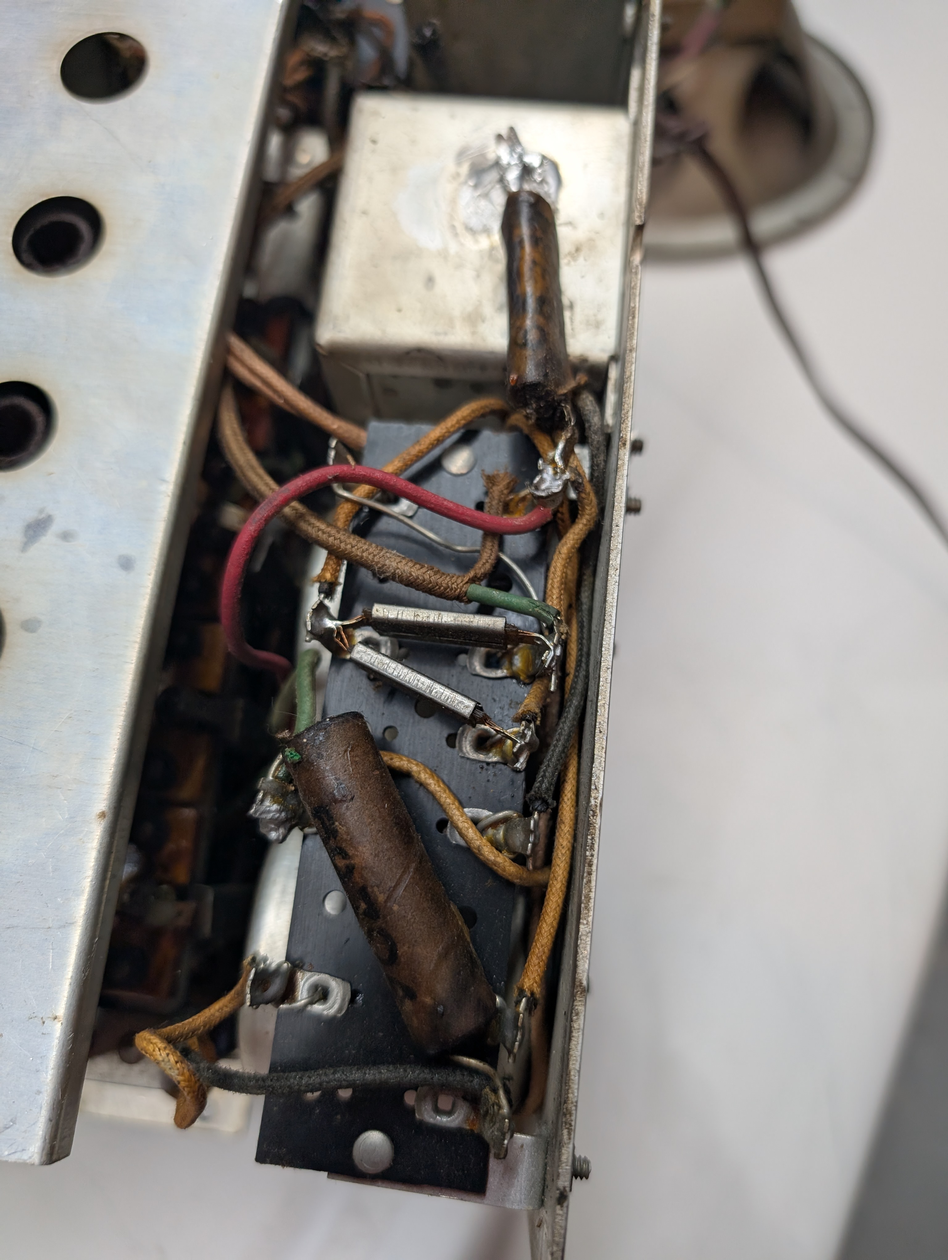
The 1M resistors being 1.2M, I am OK with it.
400 Ohm cathode resistor being 560 Ohm and 60k being 86K...I am not Ok with it. Since that much drift occurred over 90 years, I simply paralleled the resistors to bring it under compliance. Was not easy. Cut some wires, inverted the board.
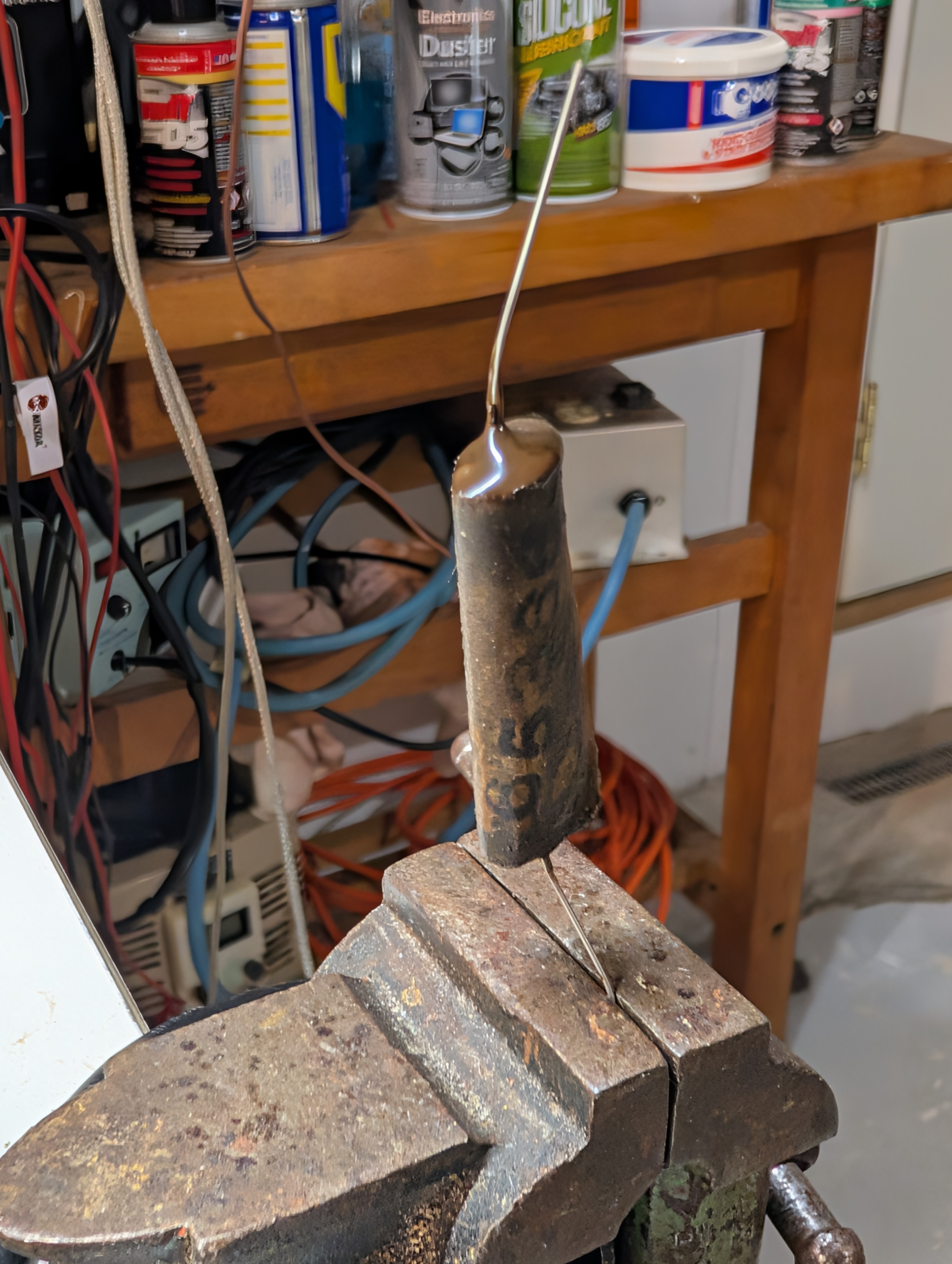
Then the caps. The caps are thin-shelled and the wax is actually tar.
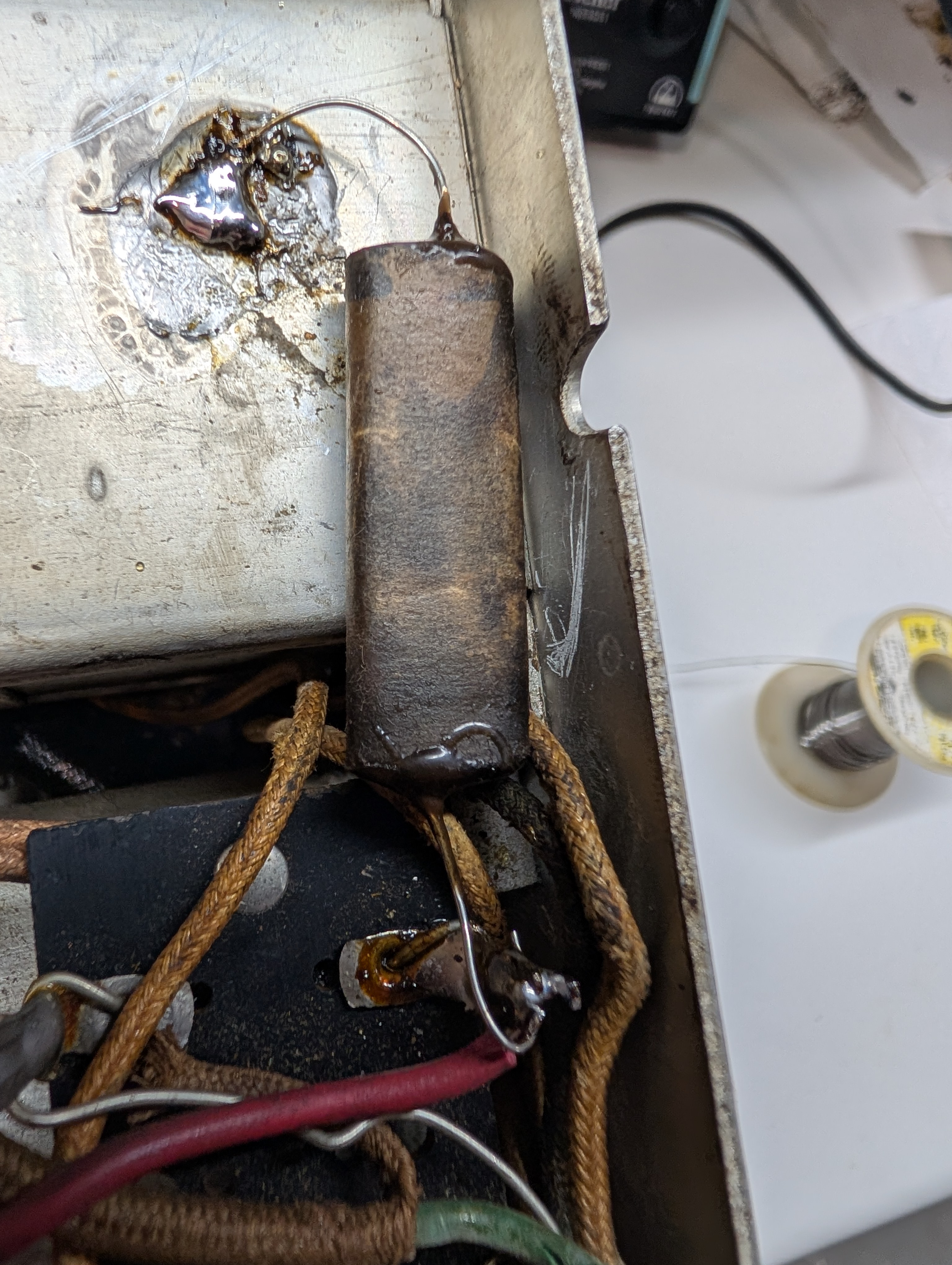
The second cap was 2,400 uuF, and upon checking it was 2,600 uuF so I was tempted to leave it in. But then I desoldered the second lead (those were two foil strips) and the value rose to 4,200 uuF, so I ended up not breaking my own rules. This cap was literally one layer of paper wrapped around the tarred innards, plus it is a mishapen flat type, not the tubular.
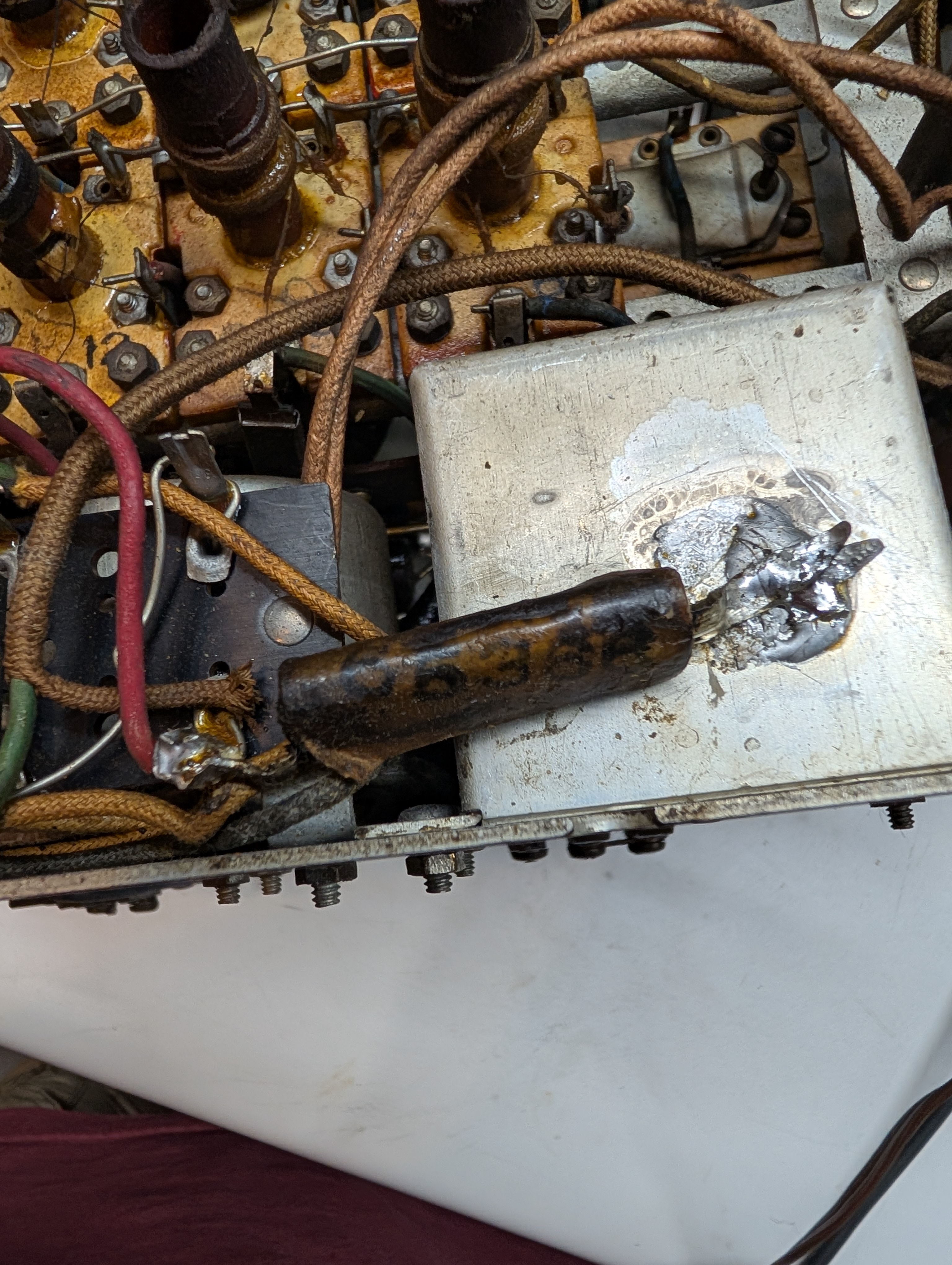
I was able to gut it.
And then I had to fold the filler paper strip (the one I put between the hot glue and the cap) instead of simply rolling it. Like so.
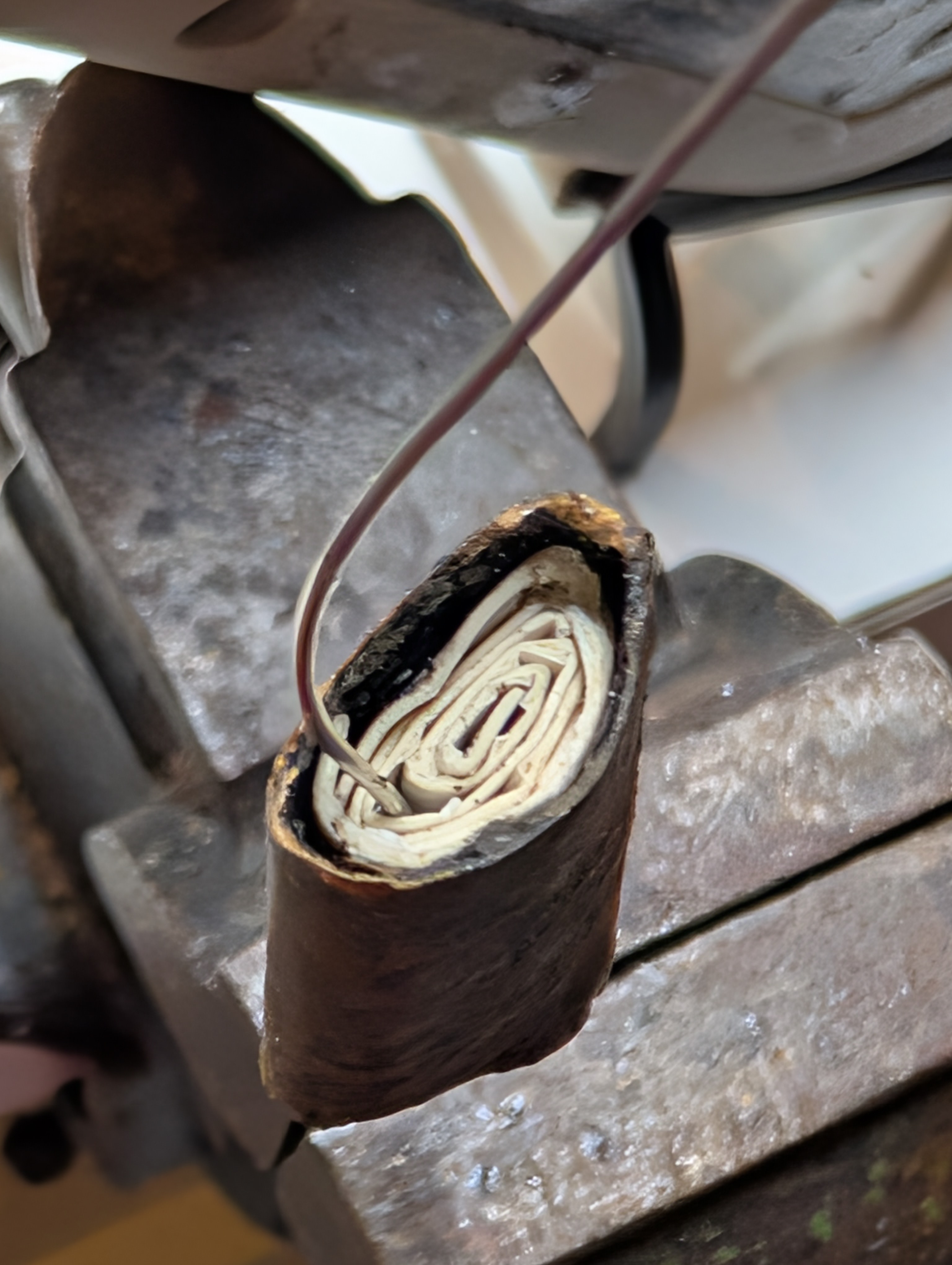
The result is this.
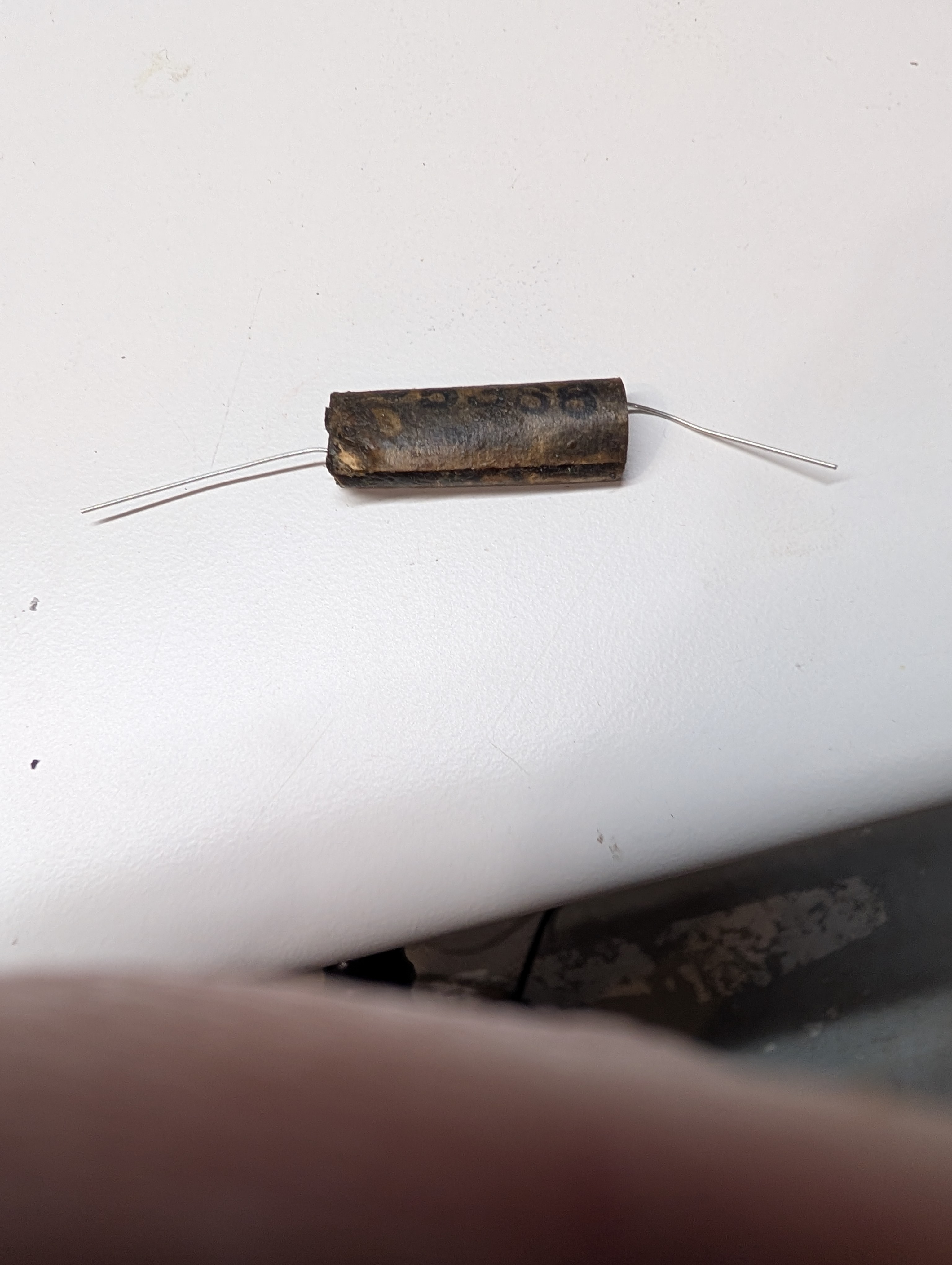
In citu
Also checked the RF antenna/osc coils (those in the shielded box), I think it's 12. All are good.
Well, that's a start.
People who do not drink, do not smoke, do not eat red meat will one day feel really stupid lying there and dying from nothing.
Posts: 3,188
Threads: 226
Joined: May 2008
City: Omak
State, Province, Country: WA
Hello Mike,
Wow, I’ve never seen a flat cardboard capacitor! Did you fill the ends with hot glue?
I melt beeswax and add color to it when I heat it up.
So, for the resistors, you paralleled some together to bring the value down to the correct level, right?
Sincerely Richard
Posts: 18,427
Threads: 622
Joined: Oct 2011
City: Jackson
State, Province, Country: NJ
Rich
Yes. 560 ohm and 2.2K give about 440 ohm which is close to where I need to be (400 ohm).
86K and 200K give 60K which is what I need (I have a bunch of new carbon resistors, and their tolerance is all over the place, so on of the 220K bunch was 200K which was exactly what I wanted).
I hotglue my caps' ends with chockolate-brown glue. I used to re-use the wax, but it never gripped right. Hotglue grips well and seals well too.
People who do not drink, do not smoke, do not eat red meat will one day feel really stupid lying there and dying from nothing.
Posts: 5,654
Threads: 56
Joined: Sep 2008
City: Sandwick, BC, CA
Mike;
The only time I had luck reusing old wax was if it came out of one of those tin can block condensers, I did that with one out of a Westinghouse 801. I actually used one of the original paper caps as filler inside the can, turning it 90 degrees and stuffing it in the bottom, then used old candle wax on top of the film caps, and some of the original stuff on top of that. I sort of had to as this can had a terminal board that needed some support. Trying to get old wax to fit inside a tube 1/2'' to 3/8'' wide is not easy, and that hard type used to fill the ends is near impossible to work with.
I will have to remember to try paralleling new resistors with old in some of my sets where they have drifted, I have a G.E set that is around the same age as your 140, and it's almost untouched underneath other then the filter caps, which look like 1950s era replacements.
Regards
Arran
Posts: 3,188
Threads: 226
Joined: May 2008
City: Omak
State, Province, Country: WA
Hello mike,
I will have to pick myself up some of that hotglue and try it out.
I too have tons of old NOS carbon resistors .
Sincerely Richard
Posts: 18,427
Threads: 622
Joined: Oct 2011
City: Jackson
State, Province, Country: NJ
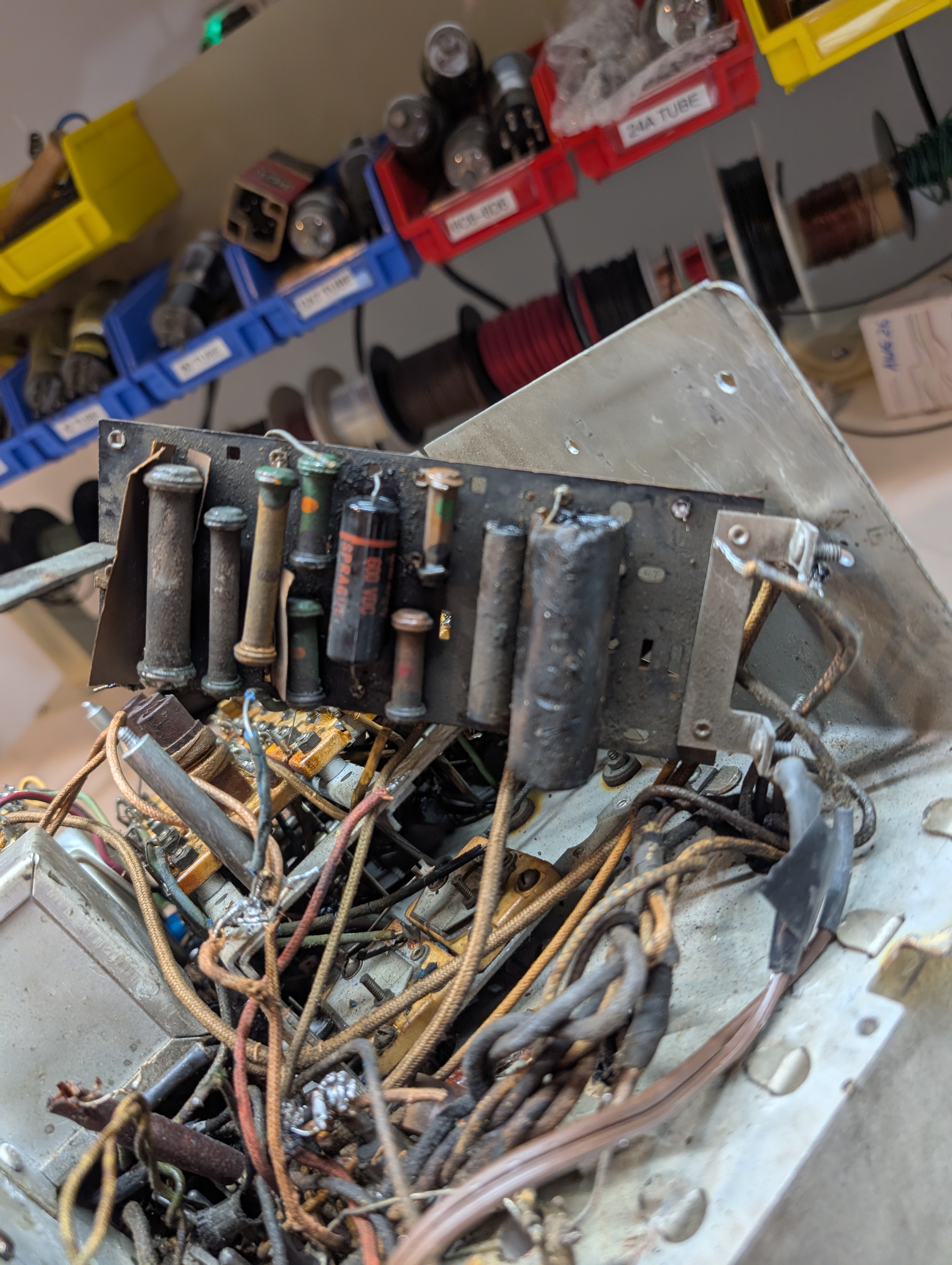
Continuing with the Resistor Board #2.
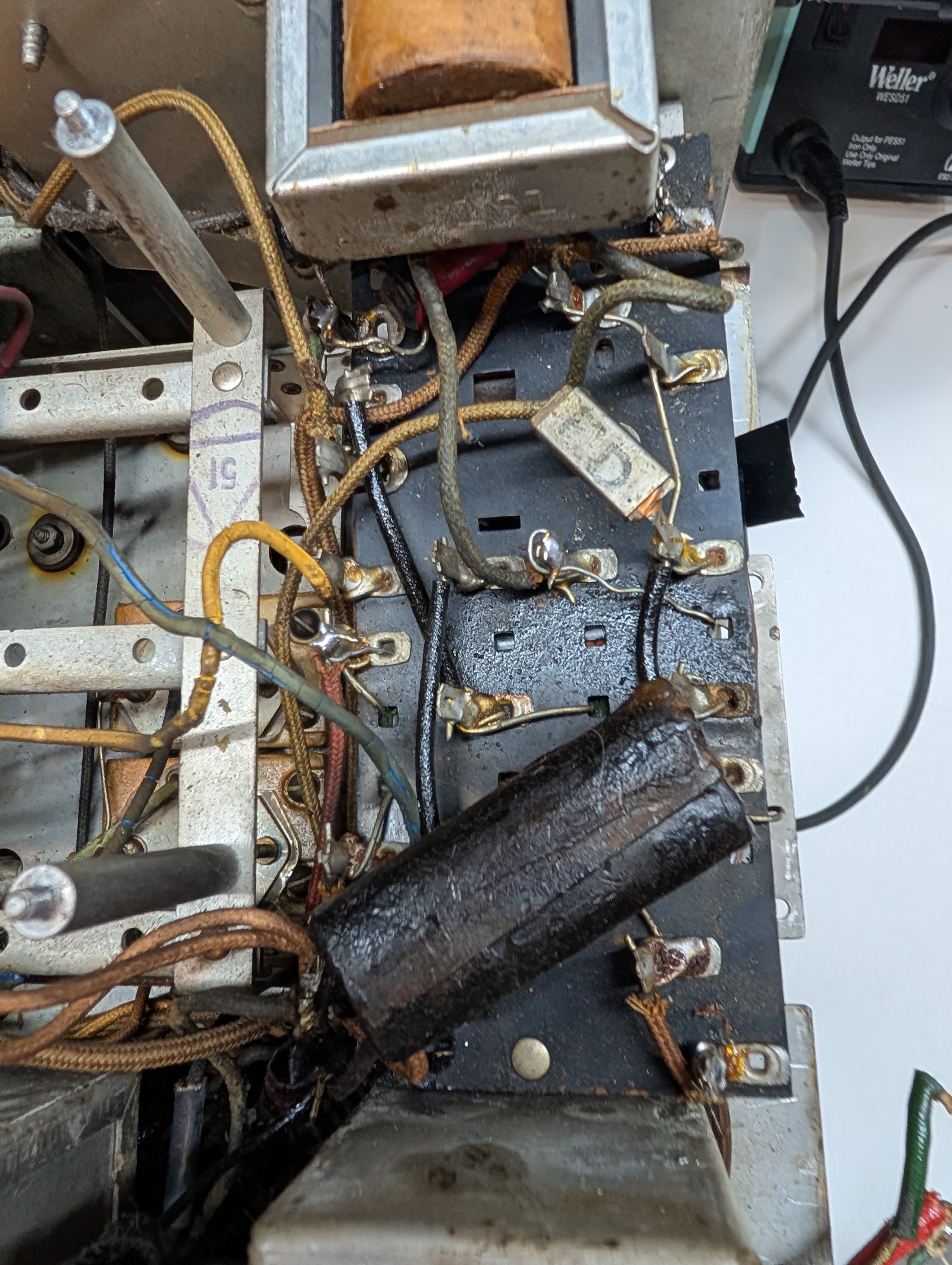
It has to be removed to be serviced.
It has three points of attachment, two at the front panel and one vertical.
Also many, many wires holdingit down.
Detached the wires, took tons of photos, though I do not see how those are going to work without tracing with the diagram.
In order to remove the board I had to remove the filter choke that kept the board from moving. It in itself was an adventure, as the choke had to move forward towards the board, with the gap between them some like 1/16". I flexed the back wall to which it was attached, but the screws (4) always tried to get back in their respective holes, so I eventually pulled two of them and inserted a hacksaw blade under them, to stop from going into the holes.
Whew.
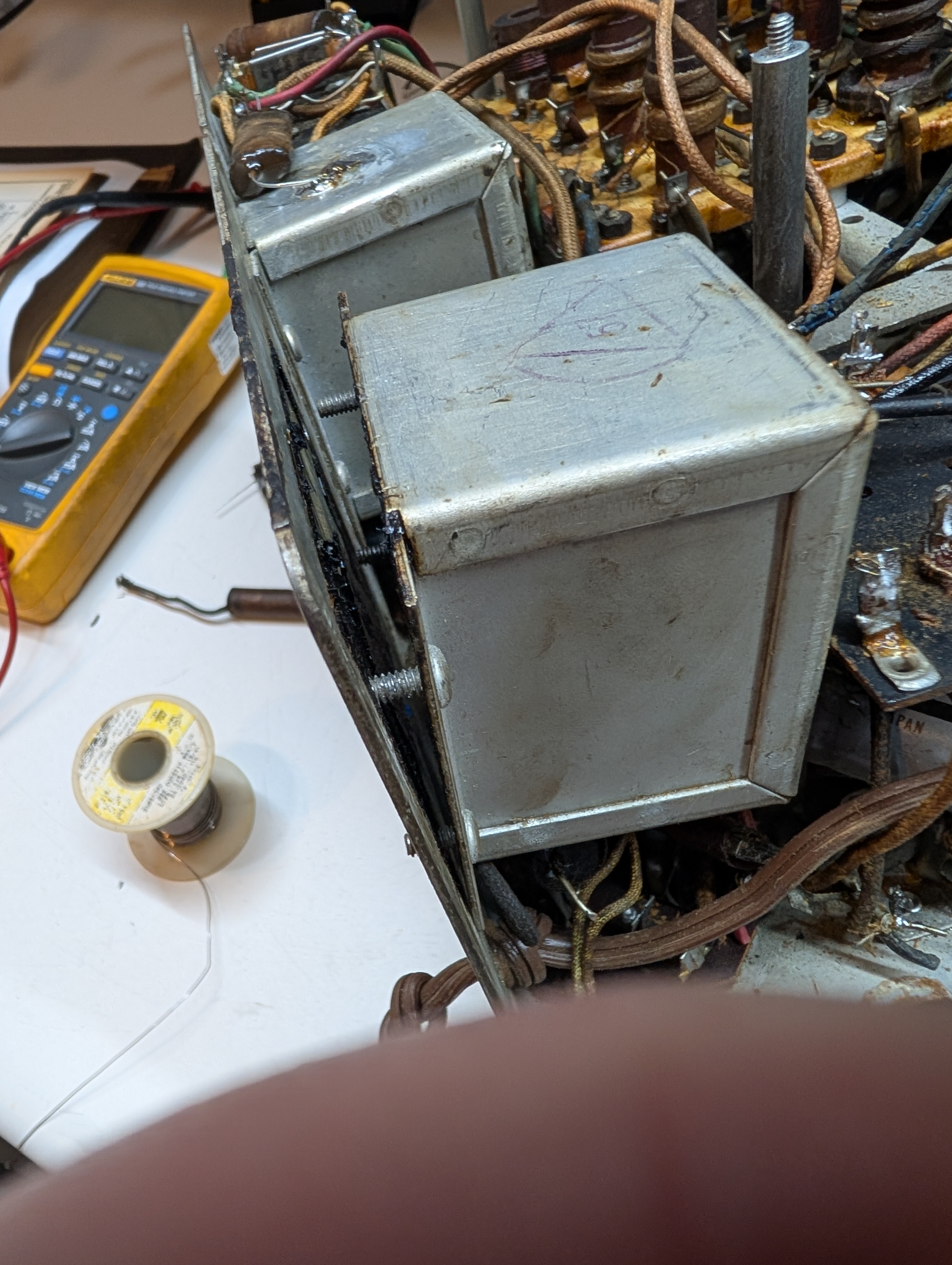
Eventually pulled out the board.
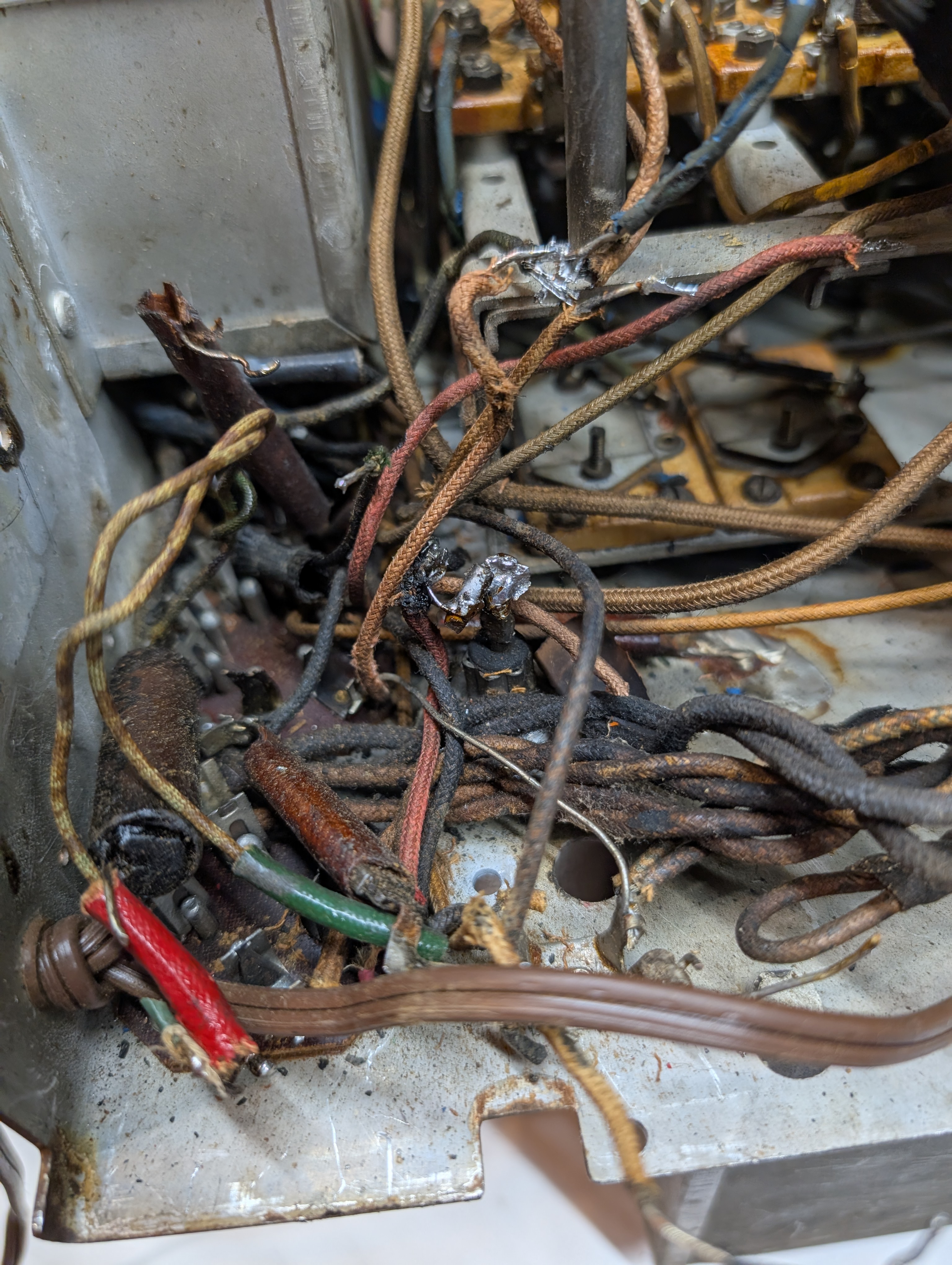
This is the mess under it.
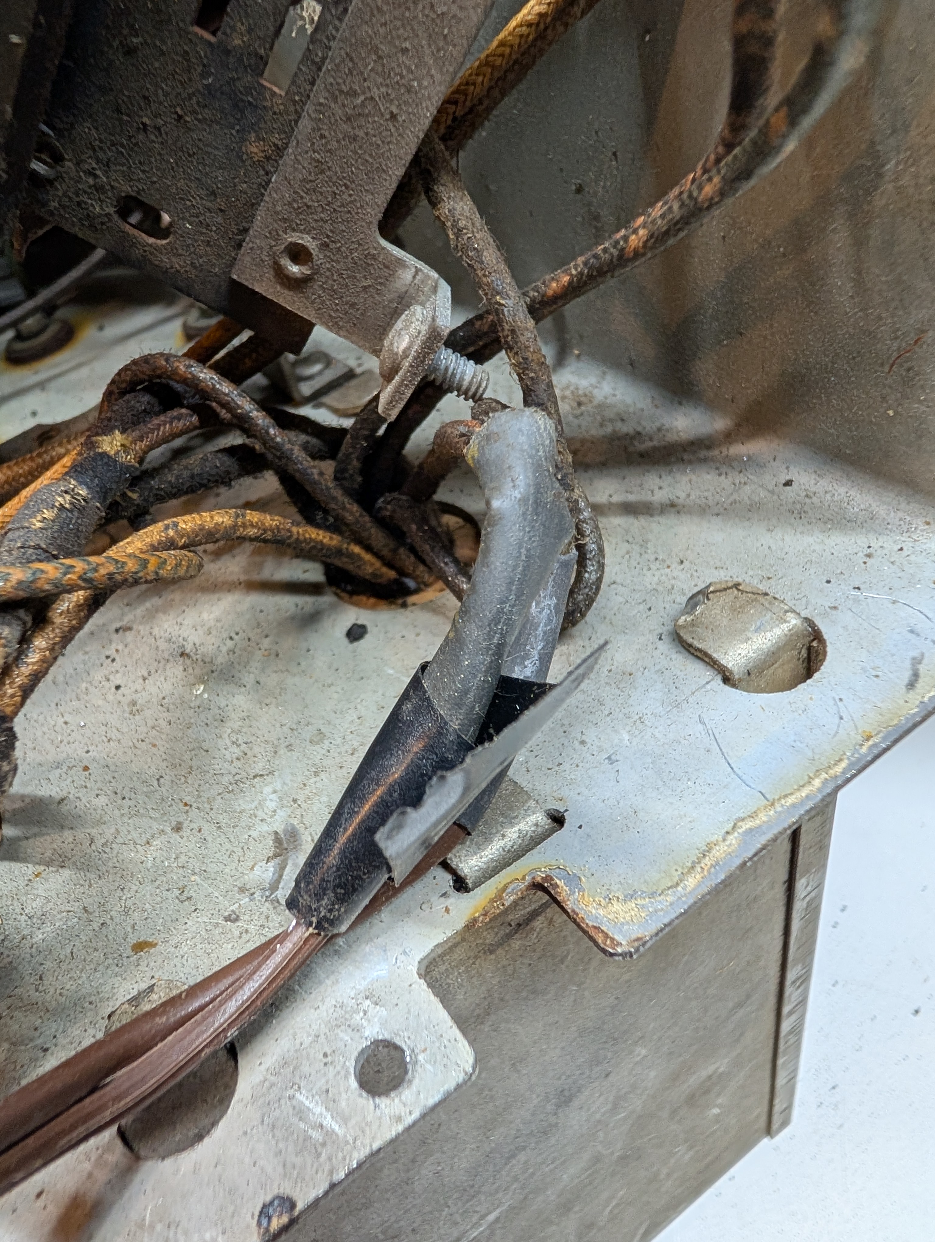
This is the way it was "repaired" before. Black tape etc.
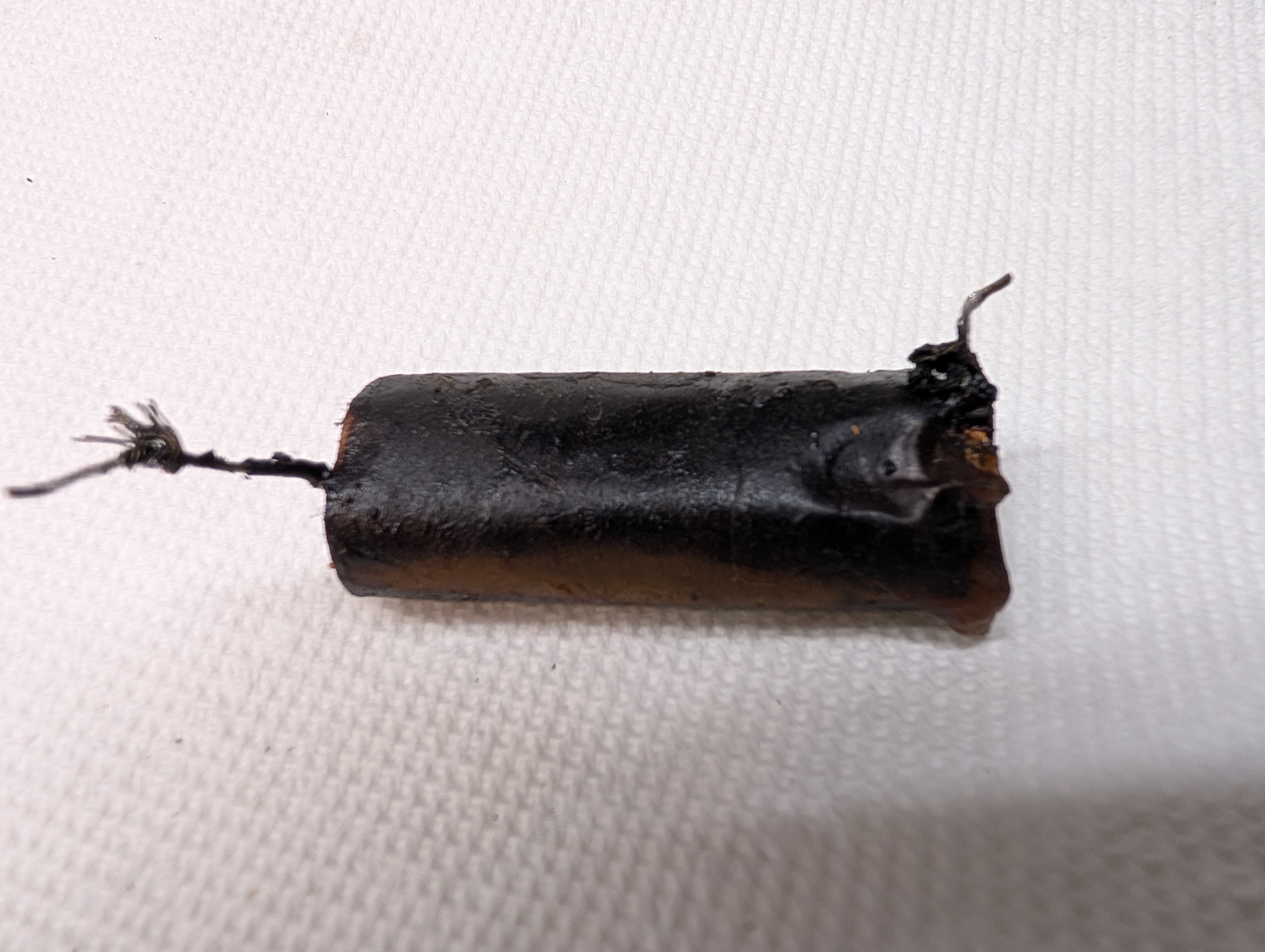
This is another "flat" cap restuffed.
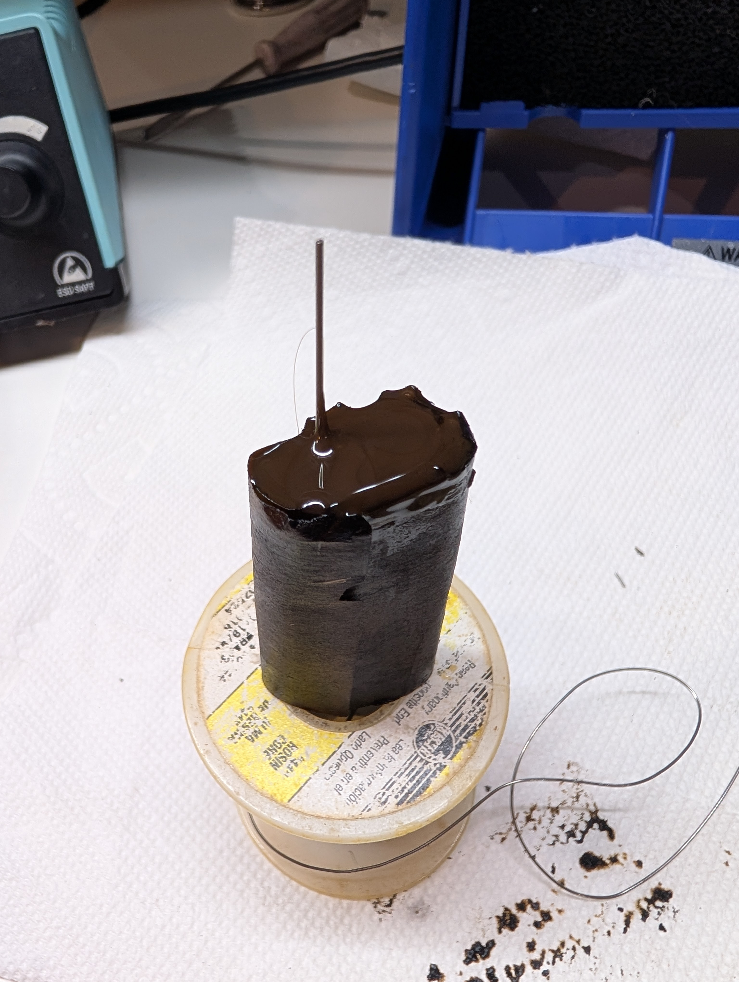
A few (not many) wires have rubber insulation. A couple are shielded (yes, shielded rubber wire).
Will have to go.
People who do not drink, do not smoke, do not eat red meat will one day feel really stupid lying there and dying from nothing.
Posts: 3,188
Threads: 226
Joined: May 2008
City: Omak
State, Province, Country: WA
Hello mike,
Is that more of that hot glue did you get that on amazon it's just brown right ?
Sincerely Richard
Posts: 711
Threads: 46
Joined: Sep 2009
City: Lapeer, MI
State, Province, Country: USA
Mike, What a mess!  Do you think that was the way RCA "engineered" the radio or the result of previous attempts to fix it? Be strong! Joe
Courage will follow when Faith takes the lead.
Posts: 18,427
Threads: 622
Joined: Oct 2011
City: Jackson
State, Province, Country: NJ
Rich
Yes, got on Amazon. Plain brown hot glue.
Joe
I suspect at least part of it was RCA's doing. Some was the result of the previous person(s) attempts to repair, but you can see that the wires are originals, and the caps are mostly original (they replaced two electrolytics), and the cord was probably changed, so the extent of the repairs was not that ...extensive.
I'll be able to assess it more accurately when I get to the 2nd and 3rd radios I have (another 140 and GE K-85).
People who do not drink, do not smoke, do not eat red meat will one day feel really stupid lying there and dying from nothing.
Posts: 3,188
Threads: 226
Joined: May 2008
City: Omak
State, Province, Country: WA
Hello Mike,
thank you, and I shook my head when I saw that mess.
more power too you for getting that sorted out.
Sincerely Richard
Posts: 18,427
Threads: 622
Joined: Oct 2011
City: Jackson
State, Province, Country: NJ
It was supposedly working.
And I have no doubt it could, considering all magnetics were fine and the new electrolytics were added.
But I call this type of restoration/repair sloppy, if not botched. This is the reason I never trust the restorations by others when I buy a set and it says "restored and working."
Simply speaking, different people have different standards, and I do not even mean the re-stuffing and such.
I mean the quality of the parts used, neatness, soldering quality, technique, things like the capacitors used in parallel to the older capacitors instead of full replacement, etc.
The radio could be working, but even a man who is clinically dead, technically is still alive. Which does not mean we want to keep him that way forever.
People who do not drink, do not smoke, do not eat red meat will one day feel really stupid lying there and dying from nothing.
Users browsing this thread: 3 Guest(s)
|
|
Recent Posts
|
|
Stromberg Carlson 1500 Squeal
|
| And life just keeps getting more complicated. By dconant.
Dittos'Jimradio — 08:01 AM |
|
Plug Voltages Needed For A 1943 CRV-20130 Power Supply
|
| That looks a lot like an aircraft connector of some kind, even if it's a U.S.N power supply. I have a book somewhere abo...Arran — 02:56 AM |
|
Plug Voltages Needed For A 1943 CRV-20130 Power Supply
|
| hello david,
I have a similar generator in my collection that features a cast iron, single-cylinder Briggs & Stratt...radiorich — 01:00 AM |
|
under chassis parts locator diagram for 1938 Zenith 9s262
|
| Has anyone gone to the trouble of creating an under chassis parts locator image? Yes, I can identify components by foll...bobloney — 08:57 PM |
|
Plug Voltages Needed For A 1943 CRV-20130 Power Supply
|
| Try looking at this site the book mark is for a old generator that I was given. David https://radionerds.com/index.ph...David — 08:36 PM |
|
Plug Voltages Needed For A 1943 CRV-20130 Power Supply
|
| Hello Everyone,
I am looking for voltage identification for all the pin positions on the socket of a CRV-20130 power su...Tonym4704 — 08:16 PM |
|
Philco P45-6365 Universal Transformer Instruction Manual
|
| Can anyone guide me to where this may be found?GRG — 03:00 PM |
|
54C Complete Teardown/Rebuild
|
| I don't think that I have encountered a 12Z3 before, curious how it uses one of those but includes a #43, which is a 25 ...Arran — 02:17 PM |
|
HiFi (Chifi) tube amp build - but my own design.
|
| It's the other forum. I'm also in DIY, but mostly read there. Honestly, I kinda jumped into this without much thought to...TV MAN — 10:43 AM |
|
Philco 71 Code 125
|
| Hello,
I am in need of a schematic for this radio. Mine has the three separate circular tube shields and a shadow me...dconant — 08:06 AM |
|
Who's Online
|
There are currently 1888 online users. [Complete List]
» 1 Member(s) | 1887 Guest(s)
|
|
|

|
 
|









