Philco 49-602; I are stymied
Posts: 2,327
Threads: 23
Joined: Jul 2020
City: Greenlawn
State, Province, Country: NY
Hi Joe,
I edited my post to add more info, not just for you, as you are advanced, but I tend to over-write for the benefit of those new to the hobby. (I'm a frustrated wannabe teacher and possibly a frustrating wannab teacher.)
I used 1.5V for the calculations as when on batteries, they actually do use a 7.5V battery.
"Do Justly, love Mercy and walk humbly with your God"- Micah 6:8
"Let us begin to do good"- St. Francis
Best Regards,
MrFixr55
Posts: 18,427
Threads: 622
Joined: Oct 2011
City: Jackson
State, Province, Country: NJ
Strictly speaking
1.4V + 1.4V + 1.4V + 2.8V = 7V.
Which is 140 Ohm.
But. There is that 600 Ohms one. Tracing it is no fun, but I think it parallels the longer branch of the filaments except the last half for 3V4
So, it is:
(28+28+28+28)||600 + 28 = 94 + 28 = 122 Ohm.
Or so I think.
People who do not drink, do not smoke, do not eat red meat will one day feel really stupid lying there and dying from nothing.
Posts: 711
Threads: 46
Joined: Sep 2009
City: Lapeer, MI
State, Province, Country: USA
Good Evening. The 49-602 is now off life support and working on its' own. I fear that I've become no better than a parts replacer, and a not very good one at that. I failed to replace R207 and I put a wire in its place  . I also failed to put a jumper connection in place. I possess the schematic, but didn't trace the circuits properly to insure that everything was as it should be. Well, the voltages are as follows:
C101A s/b 120V, measues 111V. OK
C101B s/b 65V, measures 58V OK
7.5V between Pin 7 of 3V4 and Pin 1 of the 1R5, measures 5.7V. Low, but OK
I also measured the voltage after R102. The schematic says it should be 90V, it measures 88V.
It plays rather well. I will Keep it playing for many hours over the next few days. After that I will use the battery eliminator to see how it performs that way. If it does, I will build a battery to fit in the compartment.
Thank you gentlemen and appreciate your assistance. I hope that I will be more diligent on my next radio. Joe
Courage will follow when Faith takes the lead.
Posts: 2,327
Threads: 23
Joined: Jul 2020
City: Greenlawn
State, Province, Country: NY
Hi Joe,
I don't think that the jumper in place of R207 would cause your problem unless it went direct to ground but that would not cause the filament supply to be 21V. Where was the jumper supposed to be between.
"Do Justly, love Mercy and walk humbly with your God"- Micah 6:8
"Let us begin to do good"- St. Francis
Best Regards,
MrFixr55
Posts: 711
Threads: 46
Joined: Sep 2009
City: Lapeer, MI
State, Province, Country: USA
Mr. Fixr, The schematic doesn't show a "jumper", but on Section 2 of the schematic, it is where C201, C204, C206, the black wire from Z301, R201, and R206 all connect to Pin 1 of the 1U5. There is a 6-lug terminal strip where lugs 3 & 4 should come together. One lug alone woud make a very sloppy connection indeed. I now recall cleaning both lugs and reattaching them in a cleaner fashion. I forgot about the jumper. I'm puzzled about the low A+. When calculating for the resistor drop of the 1N5408, I used:
R=drop/IDC = 10V /0.063A = 159 ohms.
The closest I could come up with was 135 ohms at 2W.
I will ponder this and maybe look for 150-160 ohms at 2W, but for now the unit plays nicely.
Thanks to all, Joe
Courage will follow when Faith takes the lead.
(This post was last modified: 05-27-2026, 11:50 AM by Joe Rossi.)
Posts: 1,797
Threads: 55
Joined: Feb 2015
City: Roseville, MN
Joe,
We've proven that restoring these is once again very humbling. Great result and it will be interesting to hear how long a battery lasts.
Posts: 711
Threads: 46
Joined: Sep 2009
City: Lapeer, MI
State, Province, Country: USA
Will do Rod. I have replaced the drop resistor of 135 ohm with two 300 ohm 5W in parallel. No voltage change except for the A+ which is now 5.65V.  Well, another day of listening to it, retracing the schematic and then running it from the battery eliminator. Now for a nap. Joe
Courage will follow when Faith takes the lead.
Posts: 711
Threads: 46
Joined: Sep 2009
City: Lapeer, MI
State, Province, Country: USA
Ran it from the battery eliminator today, everything is a-ok. When replacing the paper caps there was a non-original plastic cap marked "ASTRON". I'd never heard of the brand, it was a like-new plastic yellow .05uF @ 400vdc. The odd thing was that it measured exactly .05uF. I'm going to get to creating a battery pack, 10ea 9V and 2ea #18650 3.7V batteries for the A+. More to eventually follow. Joe
Courage will follow when Faith takes the lead.
Posts: 711
Threads: 46
Joined: Sep 2009
City: Lapeer, MI
State, Province, Country: USA
Well, Here are some pics of the battery set up I created.
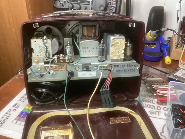
Created a new connector for the B and A battery.
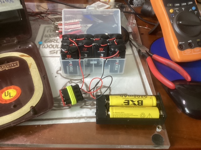
Here are the B and A battery set-up. There are 10 9-V batterys for the B and 2 18650 (3.7v) batteries for the A. The A box has on on-off switch.
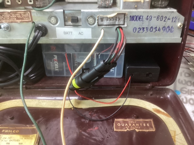
And TA-DA, here it is all put together.
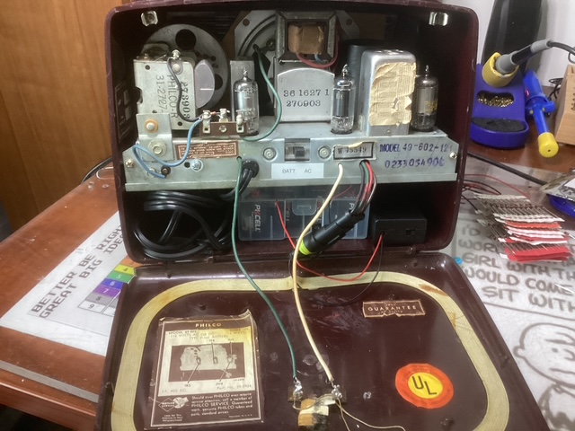
The battery set up works just ducky. However...the tuning is annoyingly scratchy below about 900kc. I have inspected the tuning-cap (with my mag-glass) for any shorts but there doesn't appear to be any. I tweaked the IF for the strongest signal, which helped overall. I'm going to shelve this for a while and come back to it. Frankly I'm tired of it, I've spent more than I wanted on it, and I need to get some patience back. Thanks for everyones help! More later. Joe
Courage will follow when Faith takes the lead.
(This post was last modified: 06-13-2026, 07:29 PM by Joe Rossi.)
Posts: 1,519
Threads: 69
Joined: Nov 2012
City: Kansas city, MO.
Nice job on the battery packs Joe.
Looks neatly done.
Posts: 711
Threads: 46
Joined: Sep 2009
City: Lapeer, MI
State, Province, Country: USA
Thanks Mike!
Courage will follow when Faith takes the lead.
Users browsing this thread: 1 Guest(s)
|
|
Recent Posts
|
|
under chassis parts locator diagram for 1938 Zenith 9s262
|
| Has anyone gone to the trouble of creating an under chassis parts locator image? Yes, I can identify components by foll...bobloney — 08:57 PM |
|
Plug Voltages Needed For A 1943 CRV-20130 Power Supply
|
| Try looking at this site the book mark is for a old generator that I was given. David https://radionerds.com/index.ph...David — 08:36 PM |
|
Plug Voltages Needed For A 1943 CRV-20130 Power Supply
|
| Hello Everyone,
I am looking for voltage identification for all the pin positions on the socket of a CRV-20130 power su...Tonym4704 — 08:16 PM |
|
Philco P45-6365 Universal Transformer Instruction Manual
|
| Can anyone guide me to where this may be found?GRG — 03:00 PM |
|
54C Complete Teardown/Rebuild
|
| I don't think that I have encountered a 12Z3 before, curious how it uses one of those but includes a #43, which is a 25 ...Arran — 02:17 PM |
|
HiFi (Chifi) tube amp build - but my own design.
|
| It's the other forum. I'm also in DIY, but mostly read there. Honestly, I kinda jumped into this without much thought to...TV MAN — 10:43 AM |
|
Philco 71 Code 125
|
| Hello,
I am in need of a schematic for this radio. Mine has the three separate circular tube shields and a shadow me...dconant — 08:06 AM |
|
Stromberg Carlson 1500 Squeal
|
| And life just keeps getting more complicated.dconant — 07:57 AM |
|
54C Complete Teardown/Rebuild
|
| Hello Roy,
here is this one
sincerely Richardradiorich — 12:45 AM |
|
54C Complete Teardown/Rebuild
|
| Richard,
Had grabbed it already but thank you just the same. I find myself wanting to find some way to block out the...glyphmon — 12:03 AM |
|
Who's Online
|
There are currently 2049 online users. [Complete List]
» 1 Member(s) | 2048 Guest(s)
|
|
|

|
 
|









