

Welcome Guest! Be sure you know and follow the Phorum Rules before posting. Thank you and Enjoy! (January 12, 2025) x


Decorative foil in some cabinets. Pt.2
#1

Hey guys,
Back in 1-2011 I posted a question on the Phorum regarding the decorative foil used on some cabinet inside bottoms. The original thread's images I uploaded are now not visible.
I cannot edit that post as it is closed to update the images, so I am posting again with the photos in case someone is interested or has an explanation.

(Original thread here on the Forum, attachments no longer visible):
https://philcoradio.com/phorum/showthrea...light=foil


 Ron Ramirez originally had no idea. The actual purpose of the foil I presume was to make a cheap shield to keep out stray RF.
But the question was why the ornate designs? Some are pretty ornate.  Myself and Ron was thinking the foil was bought by Philco from a source that originally used it as a wrapping possibly.  It would seem plausible as Philco would have no reason to emboss foil that would never be seen by the consumers.
   On the ARF an member just posted about this foil, and other than his post, I have never seen any others comment on the foil.
There is no asbe*tos under this.

So here are the original pics I posted in 2011  
Any definitive reasons for the patterns is welcome. My opinion is the decorative foil was leftovers from another company or source, Philco made good use of it for their under chassis shielding. I believe I have other patterns on disc, but cannot access them at the moment.
Thanks guys!

37-84
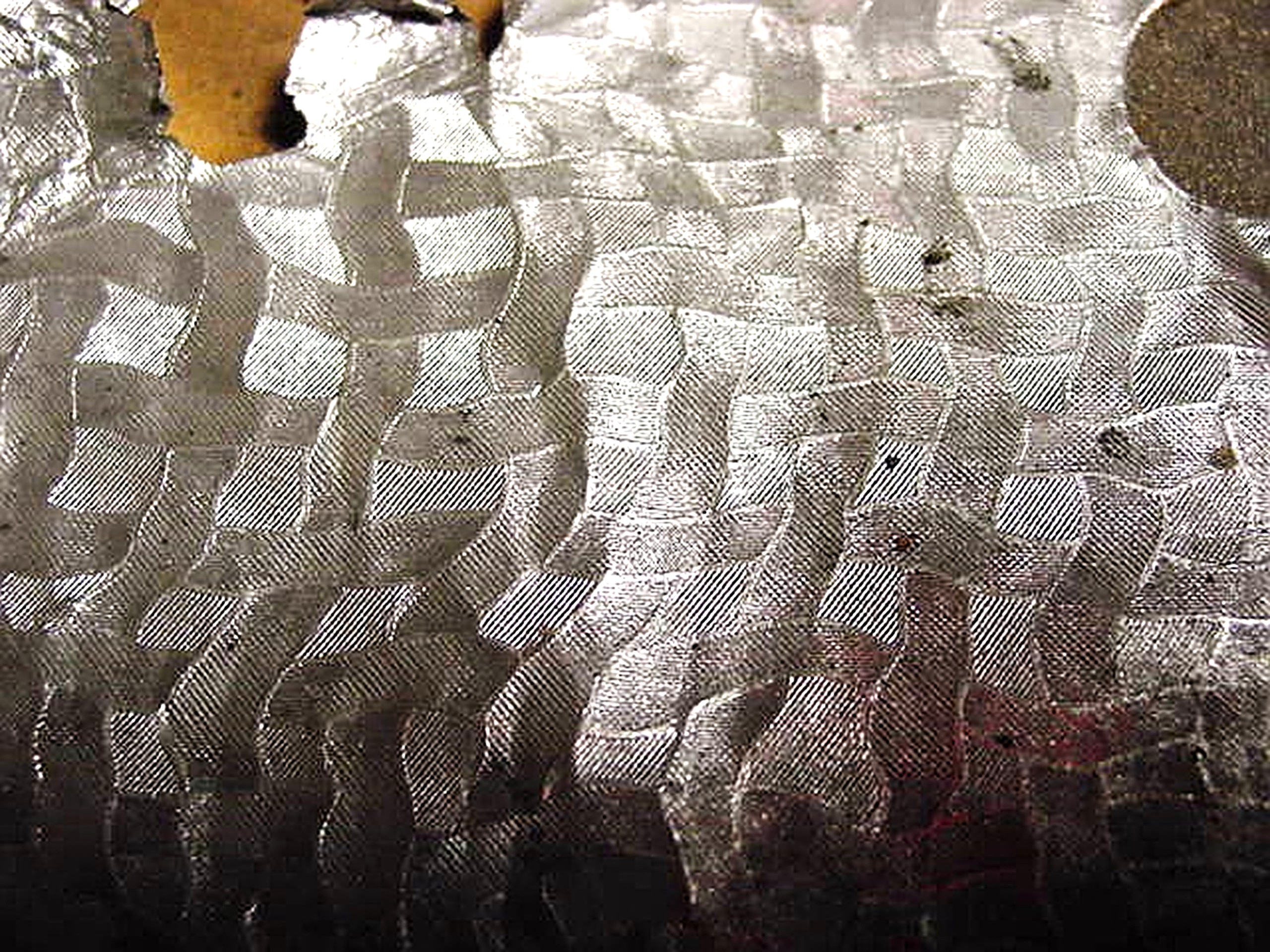
   
37-84
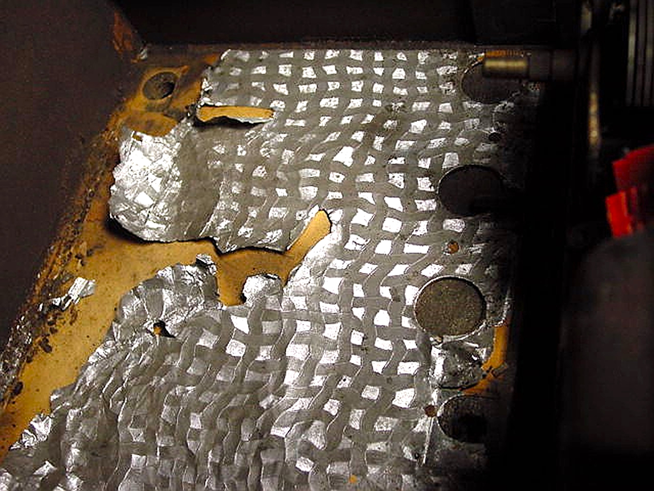
   
84B
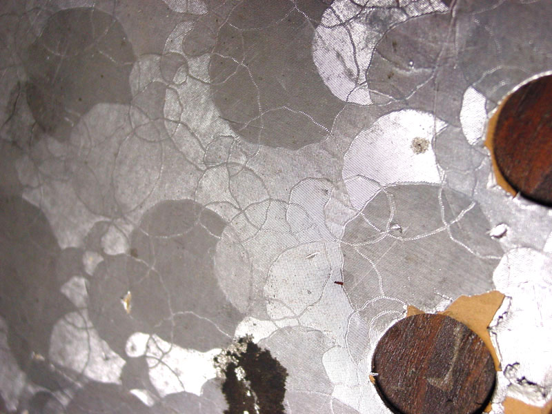
   
#2

Hello Gary,
I’ve come across similar ones on Philco radios I’ve worked on, and it was probably picked up for a bargain. I wish my grandmother were still around; I’m sure she might recognize it.

Sincerely Richard
#3

Maybe the pattern adds strength to the foil or prevents a strong em field being directed in one direction. Or when removed from the set because we have no ides make a nice tin foil hat. The foil is it alum or real tin?  David
#4

Does this foil have a paper or cardboard backing? To me it looks like the sort of embossed foil that would have been used in a chocolate box, or some other packaging. My guess is that Philco was using the same logic they used when selecting tube lineups, it was whatever they got a bargain on, or could get in quantity when they wanted it. If they needed some foil for some reason like shielding, but could get embossed stuff off the surplus market for 1/2 price, they were not above doing that.
Regards
Arran
#5

That would not surprise me at all. I remember someone (Maybe Ron Ramirez, God rest his soul) posting a note that Philco was not above splicing the magnet wire used to wind RF / IF transformers, especially single layer jobs.

Philco was a very early user of 6V tubes as they were developed for car radios and Philco was a major supplier of car radios. I believe that Philco converted to 6V tubes in transformer powered home radios in 1933.I believe that RCA did not switch over to 6V tubes on transformer powered sets until the 1935 model year, although they were using 6V tubes in series in transformerless sets, and in car radios in 1933.

"Do Justly, love Mercy and walk humbly with your God"- Micah 6:8
"Let us begin to do good"- St. Francis

Best Regards, 

MrFixr55
#6

Thanks guys for the thoughts on the foil's original use. I agree it could have been material for a candy box.
It was pretty intricate and decorative, unlike the foil from a cigarette pack or gum wrapper.

Philco no doubt didn't care what the pattern was , it was a foil that helped shield the chassis bottom from stray signals.
End runs of the stuff would otherwise be tossed by the original user,so IMHO Philco bought it.

This is one of those topics that I have not seen anywhere else.

@Arran, without going and pulling a chassis, I 'think' the foil did have a very thin backing. The entire thing was stapled to the bottom of the cabinet. I seem to remember trying to repair the crumpled foil if it was scuffed or pulled away from it's backing.
How much improvement of shielding was had, compared to a cabinet without it? I have no plans on testing that , lol
Take care and thanks to all!
Gary Maker.
#7

Hello Guys,
Yes, the candy box sounds logical!
Sincerely Richard


Users browsing this thread: 1 Guest(s)
[-]
Recent Posts
under chassis parts locator diagram for 1938 Zenith 9s262
Has anyone gone to the trouble of creating an under chassis parts locator image?  Yes, I can identify components by foll...bobloney — 08:57 PM
Plug Voltages Needed For A 1943 CRV-20130 Power Supply
Try looking at this site the book mark is for a old generator that I was given. David    https://radionerds.com/index.ph...David — 08:36 PM
Plug Voltages Needed For A 1943 CRV-20130 Power Supply
Hello Everyone, I am looking for voltage identification for all the pin positions on the socket of a CRV-20130 power su...Tonym4704 — 08:16 PM
Philco P45-6365 Universal Transformer Instruction Manual
Can anyone guide me to where this may be found?GRG — 03:00 PM
54C Complete Teardown/Rebuild
I don't think that I have encountered a 12Z3 before, curious how it uses one of those but includes a #43, which is a 25 ...Arran — 02:17 PM
HiFi (Chifi) tube amp build - but my own design.
It's the other forum. I'm also in DIY, but mostly read there. Honestly, I kinda jumped into this without much thought to...TV MAN — 10:43 AM
Philco 71 Code 125
Hello,  I am in need of a schematic for this radio. Mine has the three separate circular tube shields and a shadow me...dconant — 08:06 AM
Stromberg Carlson 1500 Squeal
And life just keeps getting more complicated.dconant — 07:57 AM
54C Complete Teardown/Rebuild
Hello Roy, here is this one sincerely Richardradiorich — 12:45 AM
54C Complete Teardown/Rebuild
Richard, Had grabbed it already but thank you just the same.  I find myself wanting to find some way to block out the...glyphmon — 12:03 AM

[-]
Who's Online
There are currently 2049 online users. [Complete List]
» 1 Member(s) | 2048 Guest(s)
Avatar

>

