


09-04-2026, 06:53 PM
Hello everyone, about a couple of months ago I bought from a local flea market a Toshiba AM/FM transistor radio Model 8P-823F that I had to buy a parts radio to get it up and running with because the original circuit board inside the radio was destroyed by battery corrosion and also the FM Antenna was broken, and so I got the parts radio board installed in the case of the radio and the new antenna and battery cover installed and the radio was working pretty well except on FM where the middle of the dial (between 90 and 100 MHz was barely getting any stations in, but yet above 100MHz and below 90MHz the radio worked fine and so I attempted to see if I could realign the radio but when I did that I ended up making it worse and so I broke down and bought the Sam's for the radio and I'm attempting to do a realignment following the Sam's but I've already ran into some typos in the Sam's where some of the oscillator adjustments seem to have been given the wrong frequency in the service data, for the upper end of the AM Oscillator adjustment they gave a frequency of 1670 kC but the radio's upper end only maxes out at 1630 kC on the AM Band so I tried 1630 and I got the signal in loud and clear whereas when I tried 1670 I couldn't get anything in on the radio as far as the signal generator went, and then I'm trying the 1400 kC adjustment and I can't get the radio to pull in the 1400 kC signal from my signal generator, it will pull in all of the frequencies around 1400 kC but it won't pull in 1400 kC. I haven't even tried the 600 kC adjustment yet and I haven't even attempted the FM Alignment yet. Any ideas as to what I might be doing wrong or how I might go about trying to get this radio aligned properly?
See Pictures below.
Any Help with this would be appreciated.
P. S. this is apparently a very rare radio, because I've not seen very many of this radio out there, it actually took me several months of scouring ebay just to find the parts unit for this radio to get it going, and the fact that its only covered in Sam's and that's it kind of goes to show this wasn't a very common radio (and was probably very expensive in its day) its a rather unique looking radio as its actually half the size of most transistor radios of its time (it only measures about an 1" thick whereas most other radios like it were about 3 or 4 inches thick at the time, and on top of that its got 2 IF Stages for the AM and 3 IF Stages for the FM, an RF Section for the AM and FM, and the audio output is rated for a 1/4 watt which is really hot considering most radios at that time barely put out an 1/8th of a watt.
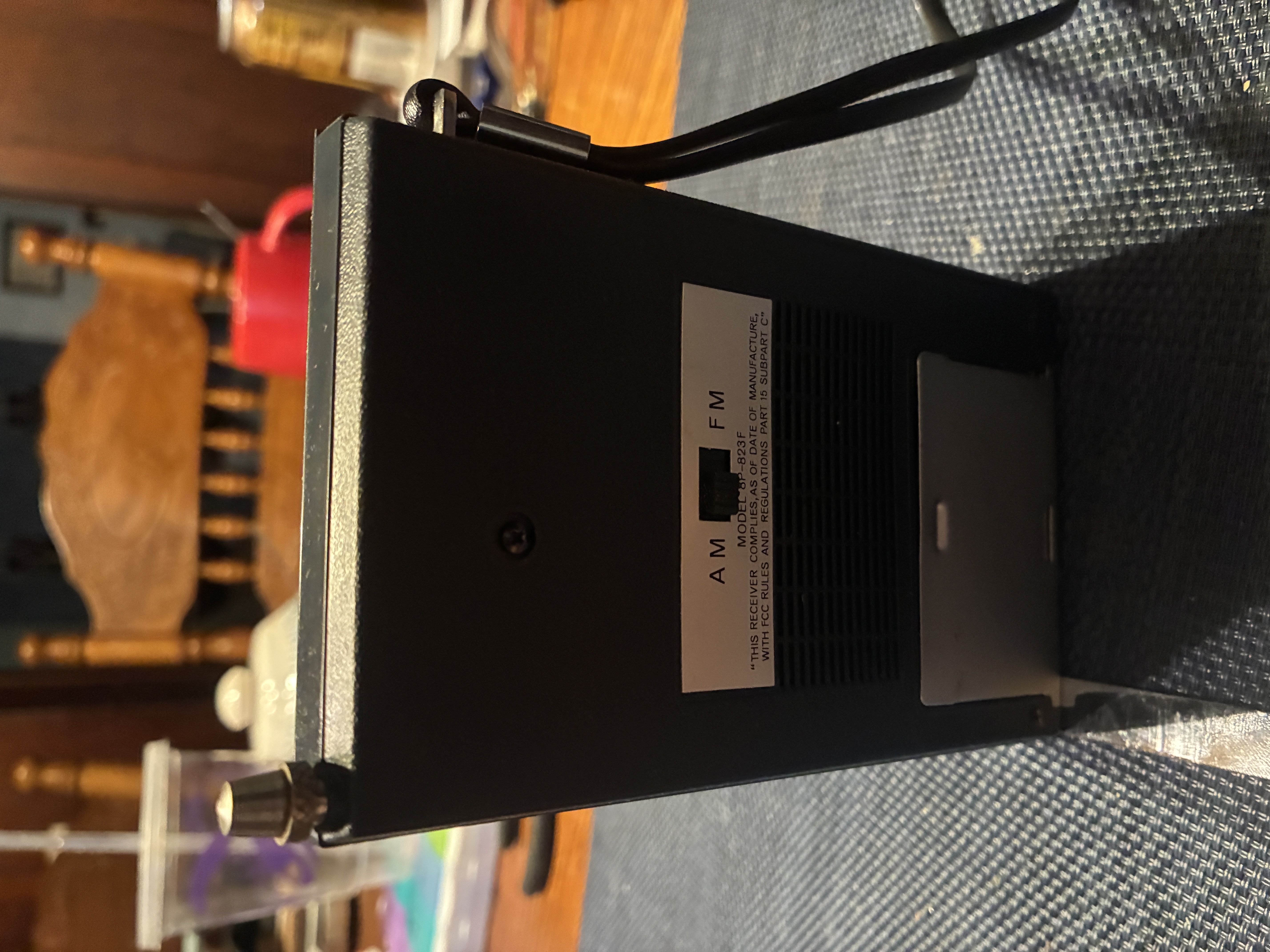
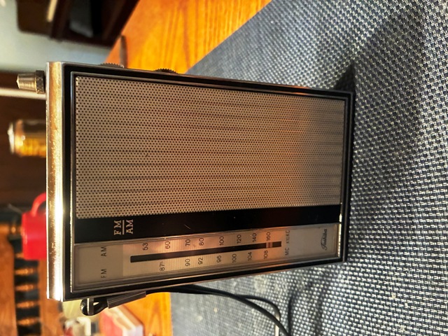
See Pictures below.
Any Help with this would be appreciated.
P. S. this is apparently a very rare radio, because I've not seen very many of this radio out there, it actually took me several months of scouring ebay just to find the parts unit for this radio to get it going, and the fact that its only covered in Sam's and that's it kind of goes to show this wasn't a very common radio (and was probably very expensive in its day) its a rather unique looking radio as its actually half the size of most transistor radios of its time (it only measures about an 1" thick whereas most other radios like it were about 3 or 4 inches thick at the time, and on top of that its got 2 IF Stages for the AM and 3 IF Stages for the FM, an RF Section for the AM and FM, and the audio output is rated for a 1/4 watt which is really hot considering most radios at that time barely put out an 1/8th of a watt.





