Hi Roy,
I apologize for the length of this post and the less than organized format. I am scratching my head a lot on this for several reasons.
I have reviewed the Nostalgia Air documents for the 96 and the similar 95. I confirmed that the set uses AVC per these documents In addition, the resistor string between the center tap of the HV secondary of the power transformer and chassis ground develops a fixed negative grid bias voltage for several tubes, including the detector-amplifier, which is further increased (made more negative) by AVC voltage on strong signals. These confirms my suppositions from my first notes, and is the reason why the plate voltage cnanges from as low as 60V to as high as 120V based on signal, that you observed.
The Nostalgia Air schematics may come from Philco, but the notes may not. They may have been written by Breitmanns, Rider or another publisher. In the case of the Nostalgia Air documents for the 95 and 96, these came from a radio course from International Correspondence Schools (ICS), Scranton, PA. Attached here is a link to the Nostalgia Air document for the Model 95 radio. You may want to read this because it is a correspondence course and the notes for the Nostalgia Air documentation for the Model 96 also come from ICS and are dependent on the following document:
https://www.nostalgiaair.org/pdfs/Philco...orp-95.pdf
Also of note is the following paragraph paraphrased from the text in the above link:
"The first 227 type tube is the detector which performs as a two element (diode) rectifier (plate and grid strapped). As a detector, it is practically linear... A special resistance coupling is used between the first (detector-rectifier) and second (detector-amplifier) 227 tubes. The detector-amplifier depends on the detector-rectifier for its grid bias. The output of the rectifier regulates the grid bias on the RF amplifier tubes this regulating the gain of the set, keeping the volume constant.
Another variable is that the voltages in these ICS documents from Nostalgia Air come from a "Set Tester" where an adapter is plugged into a socket and the tube is then connected to the set tester. I am not sure what the "reference" is; in other words, when measuring the plate voltage, is chassis ground the reference or is there another reference point, such as the center tap of the HV supply winding of the power transformer, the most negative point in the circuit. In addition, meters at this time had a rather low "ohms per volt" resistance, and could "load down" a circuit, giving an abnormally low reading. Today's modern Digital Volt Meters (DVMs) have almost infinite input resistance and will not load down a circuit. However, the difference between the specified 27V plate reading for the "detector-amplifier" and the 115 or so volts that you receive may not be explained by the lack of "loading down" the circuit with a low sensitivity voltmeter during measurement.
Another variable is reception of a signal which will definitely affect the grid bias on the detector-amplifier and therefore affect the plate voltage. If there is no signal, there is no AVC voltage. The stronger the signal the more negative the AVC voltage. As the grid voltage of the detector-amplifier becomes more negative, the plate current on the detector-amplifier will drop and the plate voltage will increase, again, explaining the phenomenom that you observed.
The following schematic does not have voltage values but does have resistance values. I don't know the original document source but this is in our Philco Library:
96.jpg (1387×1000)
Other Philco sets used this "Detector- Rectifier and Detector -Amp scheme before and since the Model 96. In the Philco Transitone 3 (one of the first auto radios and another TRF set like yours) the Model 95, the 112 and possibly others, the circuit is similar; there is no capacitive coupling between the detector-rectifier and the detector-amplifier. They are directly connected. However, for the later Model 90 (with either one or two '47 Output tubes) and others, the detector-rectifier is coupled to the detector-amplifier through a capacitor:
90c.jpg (1934×1000)
You have done a great job of signal tracing. However, I really wonder about the stated voltages from the diagram. They apparently do not come from Philco and could be based on only one radio and only one set of test equipment which may or may not have been calibrated.
To add to the knowledge base (or confusion), here are specifications for the 27 tube when used as an RF or Audio amplifier. This page is from the 1940 edition, RC14 of the RCA Receiving Tube Manual:
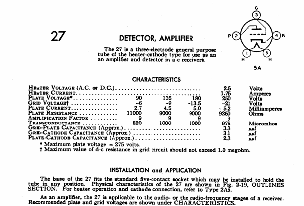
This is why I stated that the bias and plate voltages were not totally out of spec for the tube, although out of spec for the documents that you referenced.
Another variable is the field coil. If the speaker was replaced with the wrong speaker, the voltages are going to be wrong. The correct P/N for the field coil for this set is 2850. Per the following document, the correct DC resistance of this field coil is 3200 Ohms:
Speaker Field Coils – Philco Library
Although this circuit layout is documented in several Philco schematics for other models, somewhat newer sets use capacitive coupling between the detector-rectifier and detector-amplifier. Although it is controversial, you may want to add a capacitor and volume control potentiometer between the detector rectifier and detector-amplifier per the following schematic:
90c.jpg (1934×1000)
Obviously, Philco saw this as a better circuit, as they implemented it in later sets.
Hope this helps!!










