Posts: 9
Threads: 1
Joined: Oct 2013
City: Colorado
Just bought a 46-1203 from a thrift store.
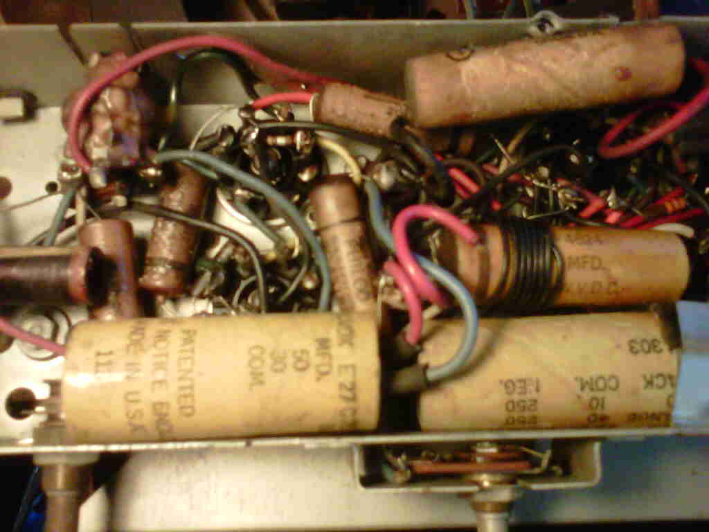
My first area to repair is the radio which has a lound hum. I opened the unit and, focusing on input power section first, I noticed the following issue:
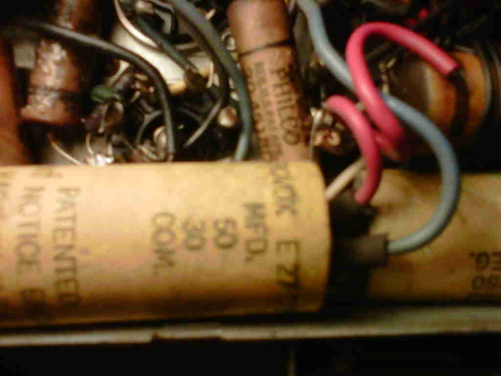
C14 to have red and blue wire on one end and black wire on the other. The red wire does not appear connected, just coiled up laying there.
Question: is this a broken wire or an extra wire?
Posts: 5,166
Threads: 273
Joined: Nov 2012
City: Wilsonville
State, Province, Country: OR
Jeff, welcome to the Phorum!! From the schematic it looks like C14 should be a single electrolytic (15mF) but C19 has two caps , 40 and 10 mF. Its possible your cap is a replacement where only one leg was used or it's the original C19 where one of the caps failed, the lead was cut and another electrolytic is tacked into the circuit elsewhere. If you order the schematic from Chuck Schwark , Philcorepairbench.com there will be more info than the schematic from Nostalgia Air. Others with specific experience with this model may have other thoughts.
Posts: 9
Threads: 1
Joined: Oct 2013
City: Colorado


Thank you for the response. I ordered the schmetics from Chuck today and will attempt to upload a photo of the radio. It is the large cap in the lower left. Its location is consistant with chassis/component diagram for C14. However I understand what you are saying about being a replacement.
Posts: 5,166
Threads: 273
Joined: Nov 2012
City: Wilsonville
State, Province, Country: OR
Looks like a replacement to me as there is no 50-30 mF cap in the schematic. You need to change out all the electrolytic and paper caps anyway. Check where it's connected to for confirmation it's C14. Replace out of tolerance resistors as you go as well.
Posts: 9
Threads: 1
Joined: Oct 2013
City: Colorado
Received the data from Chuck and now I'm ordering parts. First thing I noticed is all the reference numbers are different. Interesting. Not sure if I can find the dual capacitors (C104), if not I will use seperate caps.
Posts: 9
Threads: 1
Joined: Oct 2013
City: Colorado
Are there NOS caps available or should I just go to Digikey and get modern replacements?
Posts: 5,166
Threads: 273
Joined: Nov 2012
City: Wilsonville
State, Province, Country: OR
Jeff,
You are right, you likely will not find a dual cap replacement although there are some multicaps out there. Most folks either put in the two caps separately, or gut the old cap can or cardboard sleeve and restuff it with the new caps to look like the old one. Here are a few pics of one that I did on a 42-322.
Original in the chassis:
[Image: https://dl.dropboxusercontent.com/u/5462...iginal.jpg]
To get the guts out of this one I tried heating with a heat gun but did not get too far so then carefully drilled it out using a bit quite a bit smaller than the diameter of the cap and doing a drill/chip process to get the guts out. Anyway the cap with 3 individual caps going into it.
[Image: https://dl.dropboxusercontent.com/u/5462...lticap.jpg]
Be sure to insulate leads with heat shrink tubing. Some folks will then refill the cap sleeve with wax, hot glue, or some other filler to look like the original. I left mine unfilled so I could get back into it if there were problems. Then I refastened the cap to the chassis with the metal retaining band. Yours may or may not have that.
The other paper caps in your set can also be restuffed by heating the cap with a heat gun or hair dryer and sliding the old cap out. There are threads on this Phorum and even some YouTube videos showing people doing that. Some restuff, others just replace. Depends on your level of interest in retaining the originality of the set.
Posts: 5,166
Threads: 273
Joined: Nov 2012
City: Wilsonville
State, Province, Country: OR
Old NOS caps would most likely be faulty, use modern replacements.
Here are some capacitor suppliers:
http://www.philcoradio.com/resourceb.htm#n
I usually buy from Just Radios. Be sure you get a sufficient voltage rating on the caps you buy.
Posts: 9
Threads: 1
Joined: Oct 2013
City: Colorado
Caps on order
(This post was last modified: 10-30-2013, 12:32 PM by Colorado Jeff.)
Posts: 2,128
Threads: 18
Joined: Oct 2008
City: Merrick, Long Island, NY
+1 And you can get that cardboard sleeve looking better dunked in paint thinner (outdoors!) for a few hours and brushed off gently if need be, and dried (outdoors) for a day or so before restuffing.
Posts: 5,166
Threads: 273
Joined: Nov 2012
City: Wilsonville
State, Province, Country: OR
Thanks for the tip codefox1, I'll give that a try next time.
Posts: 9
Threads: 1
Joined: Oct 2013
City: Colorado
Thanks to this cold weather I am finally able to spend some time on the radio. The first thing I replace was the power cord. Major safety issue. Working in section 1 (Power input) the first thing I noticed was that the way in which components are wired do not match the schematics. I checked the production changes and still they do not match. While I can tune in a radio station there is a loud hum so I'm going to simply replace each capacitor one at a time while leaving the radio wired as it currently is. Any other advice is greatly appreciated.
Posts: 16,493
Threads: 573
Joined: Oct 2011
City: Jackson
State, Province, Country: NJ
Sometimes people try to improve on the power section. Sometimes they do, sometimes the improvement turns out to be the opposite of the intended.
Just check for sanity.
For example, I add a bleeding resistor across the Y-caps in parallel to the power cord contacts.
Or I added a 0.15uF cap across the filter choke in 90, improved upon AC hum.
Posts: 9
Threads: 1
Joined: Oct 2013
City: Colorado
Another noted difference. The schematic clearly shows capacitors as electrolytic. However, The parts locating diagram shows a positive direction (+) for some capacitors which the schematic does not list as electrolytic.
Which is correct, schematic or diagram?
(This post was last modified: 02-07-2014, 02:39 PM by Colorado Jeff.)
Posts: 239
Threads: 10
Joined: Dec 2013
City: Columbia, SC
Many old paper capacitors would list a ground side, which was connected to the outer layer of foil. It improved interference, apparently. The new caps polarity doesn't matter.
I don't have the schematic, but anything electrolytic is going to be obvious, with a value much larger than the .0001 - .25uf paper ones.
Users browsing this thread: 1 Guest(s)
|
|
Recent Posts
|
|
The list of my radio & TV collection!
|
| Yes, Michael. But strangely enough, I managed to keep the original veneer. I must admit that I don't really like it, so ...RadioSvit — 02:21 PM |
|
The list of my radio & TV collection!
|
| Good radio.
I bet there was a lot of veneer fixing.morzh — 02:16 PM |
|
Philco 46-480 Electronic Restoration
|
| >> it is because I am retired and a little demented.
You have just the right amount of it. No perfectly sane p...morzh — 02:14 PM |
|
The list of my radio & TV collection!
|
| Old Zenith 5S-29 tube radio. First turn-on after repair and reception quality testing. Demonstration of the operation of...RadioSvit — 01:27 PM |
|
Philco 42-345 Restoration/Repair
|
| Welcome to the Phorum, osanders0311! Regardless how far you intend to restore this set, first priority should be replac...GarySP — 11:51 AM |
|
Philco 46-480 Electronic Restoration
|
| Joseph, it is because I am retired and a little demented. My problem is that I wanted to own a collection that spans th...MrFixr55 — 11:29 AM |
|
Philco 46-480 Electronic Restoration
|
| Wow, here I am with only two restored radios. I’ve got to boost those numbers! If you can’t run with the big dogs, you m...jrblasde — 10:04 AM |
|
Philco 46-480 Electronic Restoration
|
| Hello MrFixr55,
That will for sure keep you out of trouble!
Last Sunday was spent mostly doing yard work anyway the we...radiorich — 09:50 AM |
|
Philco 46-480 Electronic Restoration
|
| Throw in all the Audio equipment that has to be kept in a bedroom (my office)L. 8 portable self contained PA speakers, ...MrFixr55 — 07:40 AM |
|
Philco 42-345 Restoration/Repair
|
| Looking at the pic supplied by Rod B, you can duplicate the missing loop antenna. 10 gauge copper wire can be used to m...MrFixr55 — 01:20 AM |
|
Who's Online
|
There are currently 1199 online users. [Complete List]
» 2 Member(s) | 1197 Guest(s)
|
|
|

|
 
|


![[-] [-]](https://philcoradio.com/phorum/images/bootbb/collapse.png)


