40-195/200/201 Rotating Antenna Label
Posts: 348
Threads: 48
Joined: Oct 2013
City: Tioga, Texas, USA
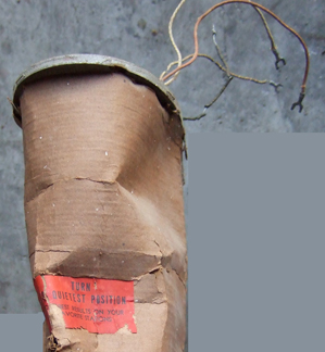
I have started a label for the part number 38-9881 rotating antenna assembly that is used on the 40-195, 40-200 and 40-201 model. It may apply to others also. What I need to know is the part no. printed on the label. On my radio, this label is cracked and damaged as is the outer cardboard covering of the assembly.

I will have to find some cardboard similar to that which was used when the radio was made if at all possible.
Can someone look at their Red with Black printing label and get the part number for the label for me. I can see this part of the number: 39-64 with the last two digits not visible.

I bought some acid free red copy paper to use in reproducing the label for the radio. It was Ampad 19611 8.5" X 11" 25 sheets available at Walmart.
Thanks in advance.
Joe
(This post was last modified: 12-05-2013, 08:18 PM by Joeztech.)
Posts: 438
Threads: 15
Joined: Jul 2008
City: Anacortes, WA
Joe--good luck on finding that cardboard. There's a wire mesh sandwiched between those two layers of heavy brown paper that is part of the antenna system. You'd be best off carefully reshaping it.
Posts: 348
Threads: 48
Joined: Oct 2013
City: Tioga, Texas, USA
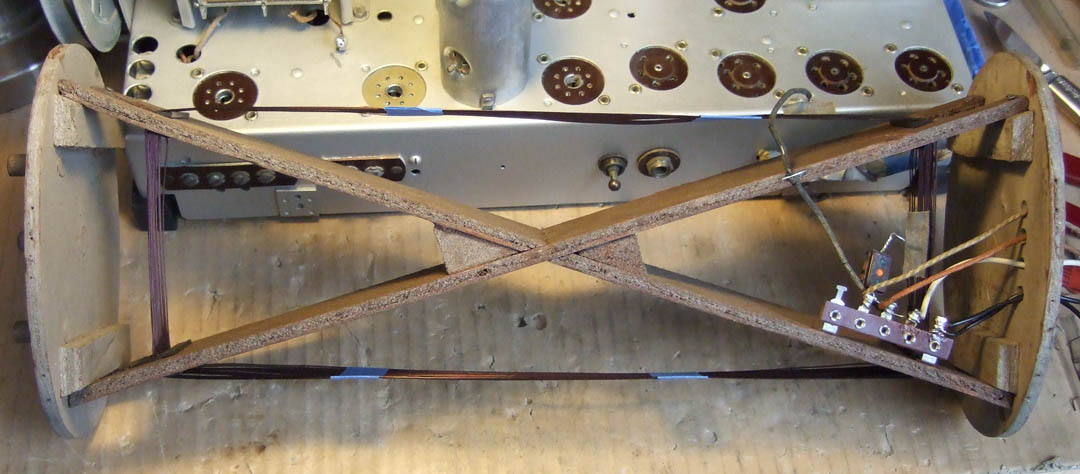
I saw one picture of it that indicated the internal loop antenna was wound around a wooden "X" shape, so that is not correct? Or is there more than one loop antenna contained within the unit? I will see what I can do with the cardboard then. Perhaps spritzing it with a water spray and waiting until it has soaked in, then trying to smooth it out. Maybe I could find a size of PVC pipe that would serve as a molding form to help keep the right shape as it dries. The cardboard has the OEM part number on it, so I would hate to loose that anyway.
Can you provide the part number of the red label?
Thanks.
Joe
Posts: 438
Threads: 15
Joined: Jul 2008
City: Anacortes, WA
The red-orange label part number is 39-6431.
I wouldn't advocate the water method; the wire mesh inside the paper sandwich should have enough rigidity that you'll damage the paper and the wire won't bend. I removed the major dents from mine by gently unstapling it from the wood frame and inching it down over the wooden ovals at the end. I also suggest taking a ruler or some similarly-sized object at this point and gently pushing the dents out from within.
The wire mesh is about as rigid as a desk staple, or perhaps a little moreso. A gentle nudge of force is required to reshape it; water won't help in the slightest.
Go gently... your paper is already brittle! Good luck!
Brandon
Posts: 348
Threads: 48
Joined: Oct 2013
City: Tioga, Texas, USA
Brandon;
Great! Thanks for the label part no. I brought the antenna assembly inside the house from the barn. It is simply too cold out there now to do any work there. I can take my time opening up the assembly and see how everything goes together. If the wire is very stiff I can understand your concerns about using any water to soften the cardboard. It looks really thin to work with.
I showed my son-in-law the progress so far on the radio chassis. He was with me when we picked it up. He could not believe it was the same radio chassis. It is nice to have the encouragement of others.
Have fun and Merry Christmas!
Joe
(This post was last modified: 12-07-2013, 02:19 PM by Joeztech.)
Posts: 348
Threads: 48
Joined: Oct 2013
City: Tioga, Texas, USA
After a closer look at the unit I found that there is a tear completely through a number of the wire strands embedded in the outer tube. It appears that there are individual wires that circle around the outer cover and are soldered to a long tinned copper foil strip that runs vertically close to the stitched seam in the outer cover. This tinned copper strip is in turn soldered to the black wire at the top. As I straightened the shape of the bent portions of the antenna assembly, the paper cracked every time I flexed it. It appears that the best way to repair this, after I get as much straightening as I can done, will be to reinforce the outer and inner walls using some brown paper similar to that used in brown paper grocery sacks. The fine wires in this outer paper shell are copper and look to be something on the order of n. 28AWG, which is pretty delicate to work with.
Does anyone know if this outer wire grid is supposed to be an electrostatic shield? I remember running into something like this on some Detrola Hotel pay-to-listen radios that also had rotatable antennas to minimize static electrical interference. I don't believe these wires are part of an actual coil, just a shield arrangement, because there does not appear to be any spiral or coiling involved from top to bottom, just curved to fit the oval shape of the outer cover.
Joe
Posts: 348
Threads: 48
Joined: Oct 2013
City: Tioga, Texas, USA
The top and bottom edges of this paper covering (it is not cardboard after all) were very brittle and crumbling with age. I found some paper grocery sacks and have cut a piece about 6 inches square, folded it in half and applied Elmer's white glue between the halves. Then I spread the same type glue on one surface and worked it underneath the top edge of the oval cylinder. As the glue was beginning to set, I kept pressing the outside of the cover against the glue surfaced paper sack reinforcement using some wooden rulers and some popsicle sticks. I will add additional patches like this all the way around the top of this outer paper cover. When I get the top end suitably reinforced, then I will do the same to the bottom of the paper cover until there is some strength to the outer paper cover at both ends. The gaping hole about 5-6 inches down from the top on one side is the biggest problem. I will try to fish the broken copper wire leads out enough to solder some connecting strands across the gap an attach to the mating end on the other side. It is going to be a delicate procedure. I will have to find some way to reinforce the inside and outside once I get the wires repaired. I may get lucky enough to slide the whole outer cover off of the wooden form to get at the inside. That would really be best as I could do a good job of reinforcing the inside to offset the external cracks on the outside. Perhaps some coffee filter paper can be used to reinforce the outer paper skin after I can get the inner surface reinforced and strengthened.
What a mess someone made of this poor antenna assembly! 
Joe
(This post was last modified: 12-07-2013, 04:24 PM by Joeztech.)
Posts: 13,776
Threads: 580
Joined: Sep 2005
City: Ferdinand
State, Province, Country: Indiana
Joeztech Wrote:Does anyone know if this outer wire grid is supposed to be an electrostatic shield?
Yes, it is. The actual loop antenna inside the electrostatic shield covering will work without it. I have one I use for test purposes sometimes; it has no covering at all.
--
Ron Ramirez
Ferdinand IN
Posts: 348
Threads: 48
Joined: Oct 2013
City: Tioga, Texas, USA
Ron;
You confirmed my suspicion on this. The electrostatic shield is never a completely closed loop. One end is always left dangling electrically, but it provides an electrostatic shield that minimizes interference from florescent lamps and neon lights and somewhat against sparks jumping from poor electrical connections. If I remember correctly this was developed shortly before WWII and at first was intended for the military, but wound up being applied for AM radio. It shows that Philco engineers were staying on top of new developments just as they did earlier in the 1930s. They had a top notch group of engineers and technical staff. Philco appears to have developed this idea and patented it. See: http://www.freepatentsonline.com/2273955.html
The electrostatic shield combined with the ability to rotate the inner loop so that it is parallel to the originating signal captures the best most noise free signal.
Joe
(This post was last modified: 12-07-2013, 08:22 PM by Joeztech.)
Posts: 13,776
Threads: 580
Joined: Sep 2005
City: Ferdinand
State, Province, Country: Indiana
It amazes me how Philco went to all that trouble of developing a loop antenna with static shield for most of their 1940 models, even patenting the idea, only to discard it the following year (1941 season) and switch to a very simple loop with only a few turns of heavy wire.
--
Ron Ramirez
Ferdinand IN
Posts: 1,114
Threads: 14
Joined: Feb 2013
City: Irvington, NY
The low impedance loop of the 1941 and later sets eliminated the need for the electrostatic shield by virtue of its design. Because it consists of only a few turns of very heavy wire, it presents a very low impedance to electrostatic fields, effectively shorting local interference to ground.
In order to bring the desired radio signals back up to useable level, the low impedance loop is connected to a step up tuned transformer in the mixer grid circuit, matching to its high impedance. In this way, interference rejection is achieved without the electrostatic shield and sensitivity comparable to the previous multiturn loop is maintained.
The low impedance loop and the low noise XXL triode mixer were real innovations that were far ahead of the conventional front end designs of the time.
Posts: 348
Threads: 48
Joined: Oct 2013
City: Tioga, Texas, USA
Yes, note the relatively short and lower impedance whip antennas used on automobiles which work quite well. The electrostatic shielded loop antenna did offer some advantages with existing designs at the time. Circuit improvements such as lower noise mixer and RF stages combine to permit better reception of lower level signals. I note that I.F. stages reduced from two to only one. The R.F. stage even in this set only has the grid circuit tuned by variable capacitance while older sets had both grid and plate circuits tuned. Of course the All-American-Five designs essentially did away with a separate R.F. stage and achieved fairly decent reception for the majority of people who lived in cities. There was less interest in shortwave reception after the war and since it cost more to build, most manufacturers quit offering sets that would tune them in.
Did any of the 1939 models have this electrostatic shielded antenna design?
Joe
Posts: 348
Threads: 48
Joined: Oct 2013
City: Tioga, Texas, USA
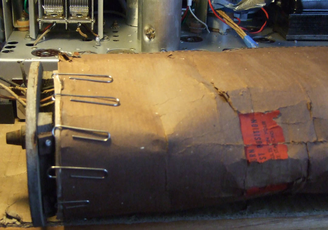
Here is a picture of the technique I am using to repair the paper covering of the antenna assembly. The paper is so brittle I am reinforcing it from the inside first at the ends. I am using grocery paper sack paper folded with Elmer's glue inside, then coating one outer surface, positioning it using tweezers and my fingers and securing it with paper clips. Once I get both ends reinforced I will be able to get to the center areas of the antenna assembly outer cover and make repairs there. The whole outer paper covering is quite delicate and will not stand much handling without disintegration. Since this may have been a one year feature, I want to preserve its function as much as possible.
Joe

Posts: 13,776
Threads: 580
Joined: Sep 2005
City: Ferdinand
State, Province, Country: Indiana
Excellent explanation of electrostatic shielding, gentlemen, thank you.
I am only aware of two Philco sets that had built-in antennas in the 1939 season - the 39-71T and 39-72T portables. All other 1939 Philcos were still designed for longwires. The loops in the 39-55 and 39-116 were only used to receive the pulses from the Mystery Control remotes.
Joe - yes, only the 1940 Philco models used that type of loop.
--
Ron Ramirez
Ferdinand IN
Posts: 348
Threads: 48
Joined: Oct 2013
City: Tioga, Texas, USA
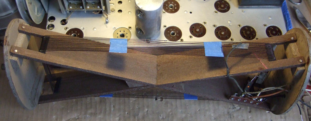
For posterity, I made measurements of the rotatable loop. The dimensions given are just to the corners of the rectangle formed by the internal wooden "X" at the point where the wires bend over the edge: 13.75 inches high by 4.5 inches wide. The distance the wires are evenly spaced across is about 1.25 inches. There is about 1/16 to 3/32 of space between winding loops. Philco used some white tape about 1/3 the distance from the corners along the 13.75 inch height to keep the wires spaced properly so that there are two bands of tape on either side of the loop (total of 4 bands of tape). The total windings are 17. The first loop beginning with the black wire is 3 turns, the second portion is an additional 7.9 loops with the final portion 6.1 turns. The wire connected to the first loop tap is the white - yellow (or in this case just white), the second portion tap is the white - red (or in this case just red) and the remaining tap at the end is the white - green wire. On this radio the black wire and the white wire were the rubber insulated types. The red wire and the white - green wires were cloth covered types. The white wire connects to the junction of the 250pfd cap and the 10k ohm resistor and is brought out to the terminal at the back of the chassis. The white - green wire connects to terminal 1 of the 4-terminal strip. the white - red or red wire connects to terminal 2 of the 4-terminal strip. The white wire from the junction of the 10k ohm resistor and 250pfd cap connects to the 2nd. terminal (right side terminal) of the 2-terminal strip to the right of the 4-terminal strip location. The wire used for the loop is 21AWG magnet wire, measuring about 0.029 inches in OD. Each section of the loop measures in fractions of an ohm.
There is one loop shown close to the dashed lines of the rotatable antenna and this loop is in the top of the cabinet with a cloth covered wire brought down to connect at the 3rd. terminal next to the 4th. terminal where the black wire connects to the terminal strip with 4 terminals. This is the loop shown on the schematic with a resistance of less than 0.1 ohms. I have not looked to see how many turns, how spaced or what wire size was used yet. That item is still in the cabinet and it is in the barn. It is still freezing outside and it will have to wait until the weather is warmer.
Joe


(This post was last modified: 12-08-2013, 02:49 PM by Joeztech.)
Users browsing this thread: 1 Guest(s)
|
|
Recent Posts
|
|
HiFi (Chifi) tube amp build - but my own design.
|
| Well, maybe - maybe not :lol: It's been an interesting project so far! Something so simple, yet so cranky. The 1st one ...TV MAN — 05:12 PM |
|
1949 Motorola 5A9M
|
| Haven't thought of Burgess batteres in a while
https://www.radionostalgia.ca/lib/Images/battery/us/burgess1D.jpgi
...Vlad95 — 03:50 PM |
|
Philco Model 16 wiring question
|
| Measure the voltages first, just in case.morzh — 02:19 PM |
|
1949 Motorola 5A9M
|
| Haven't thought of Burgess batteries in a while Mr. Fixer. Boston Edison always used Burgess in their Bright Star yellow...Paul Philco322 — 02:17 PM |
|
1949 Motorola 5A9M
|
| Thanks Sam. I'll let you know. I can probably scare some up from the local radio club.klondike98 — 02:07 PM |
|
Philco 89 Code 123 Osc Coil
|
| Hello,
I thought I would post my findings on my bad oscillator tickler coil. There were 27 turns on the outer coil b...dconant — 12:38 PM |
|
Philco Model 16 wiring question
|
| Thanks Morzh. So it appears I did wire it incorrectly and I have to switch the wires between pins 2 and 4.bobclausen — 09:24 AM |
|
Philco 46-1209 strange behavior
|
| No, it's not a problem, just during certain condition it could show up.
Yes, an internal tube short could do that too.
...morzh — 09:13 AM |
|
HiFi (Chifi) tube amp build - but my own design.
|
| You sound guys are never satisfied. :crazy: :clap:RodB — 09:10 AM |
|
HiFi (Chifi) tube amp build - but my own design.
|
| I got some new ceramic octal tube sockets installed and also tried some different coupling caps.
The results:
The go...TV MAN — 08:42 AM |
|
Who's Online
|
There are currently 1252 online users. [Complete List]
» 2 Member(s) | 1250 Guest(s)
|
|
|

|
 
|


![[-] [-]](https://philcoradio.com/phorum/images/bootbb/collapse.png)


