12-22-2013, 11:05 AM
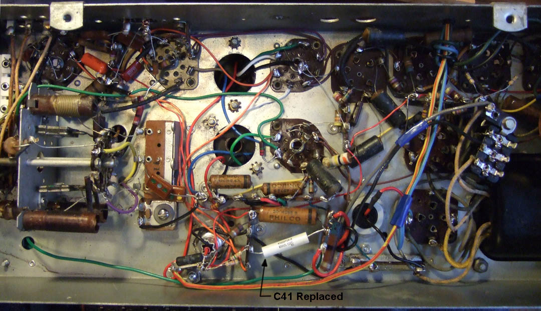
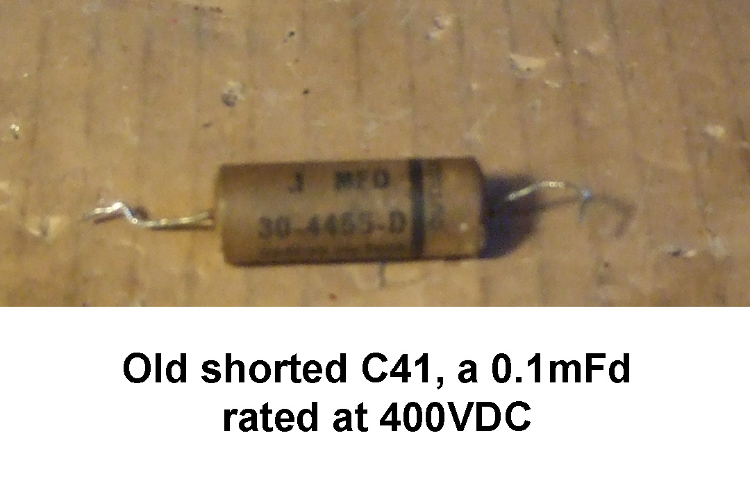
I was replacing various portions of B+ wiring on the 40-201 chassis and decided to take advantage of a lull in the work by checking resistance from various B+ points to ground to verify my work. I discovered that on the B+ line going to the IF and Mixer-Oscillator circuit had a short to ground. I had replaced R40 because it had increased in value more than 20% already. I disconnected the lead going to the two tubes and the short to ground was still there. I found that C40, a 0.1mFd @ 400VDC had shorted. I had ordered a 0.1mFd @ 600VDC to replace it if it was bad, so I had one on hand and replaced the offending part.


It is always a good idea to check for potential shorts before applying power to a chassis. After this capacitor was replaced there are no longer any shorts to ground on the B+ lines in the chassis. I will make one more check with the speaker assembly connected to make sure there are none in the field core.
I did not have a 4.7 ohm resistor to use in a negative feedback circuit to the volume and tone control circuits, but I did have some 10 ohm 5% resistors on hand. I connected two in parallel to make a 5 ohm resistor. I had a 68 ohm resistor already on hand and used it and the two 10 ohm resistors in parallel to create a feedback circuit similar to Philco sets in the late 1940s. The audio output transformer used in this set was a Stancor A-3823 replacement which did not have the needed feedback tap on the secondary windings. The addition of this feedback network will restore negative feedback and keep the distortion to a minimum like the designers intended.
I also removed the existing phonograph jack and control switch on the back of the chassis. I did some checks with my ohm meter and had discovered that the switch, which interrupted the cathode circuit of the mixer-oscillator and IF amplifier was intermittently open. Rather than try to find a new switch to use in the circuit, I decided to rewire those circuits to be like they were originally. I might still add a phonograph jack, but it will be an RCA type jack and not the 1/4" size phone jack that was used.
Joe


![[-] [-]](https://philcoradio.com/phorum/images/bootbb/collapse.png)


