Thread Rating:
  • 0 Vote(s) - 0 Average
  • 1
  • 2
  • 3
  • 4
  • 5

cap questions on model 89 (version 6 schematic)
#1

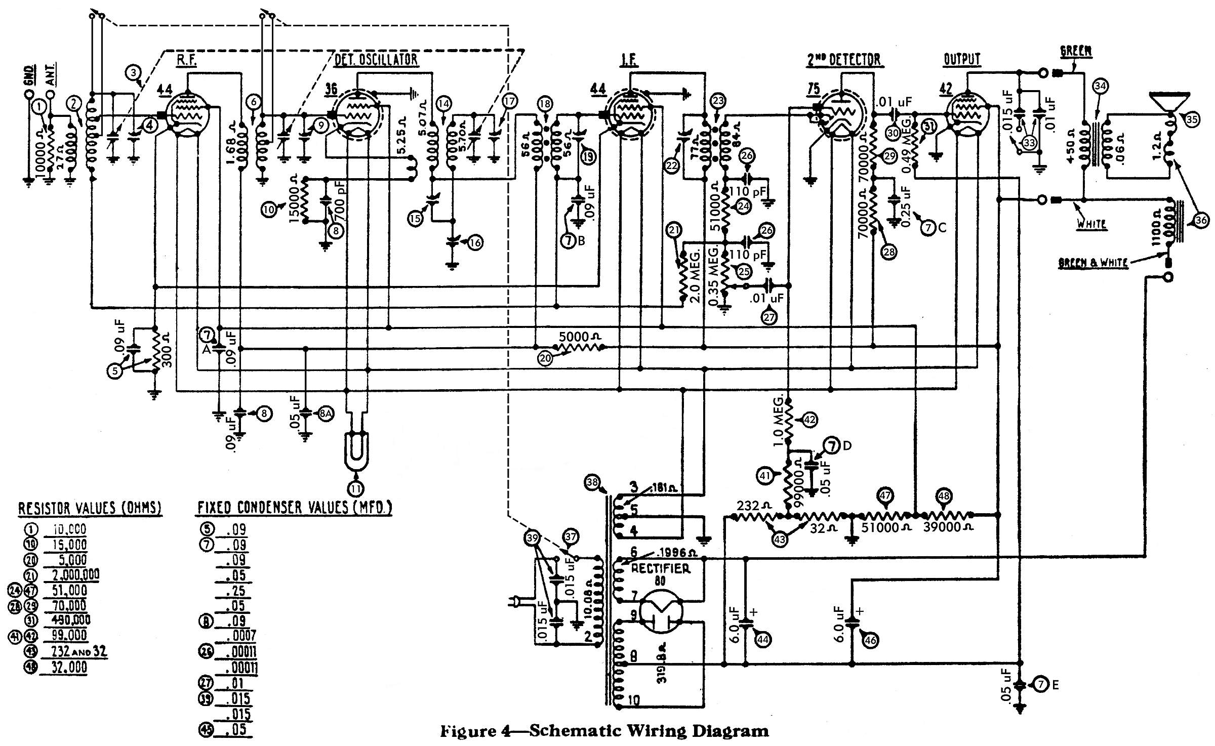
I really could use another pair of eyes and some good advice here from those more experienced than I. I'm trying to replace the caps in the #7 Filter condenser bank. There are 5 caps in that "bank", each are number 7 on the attached schematic. I'm trying to find where the .09 mfd's go? It almost looks like two of them go to the #44 RF tube on the front corner of the chassis. The other end goes to ground, of course.

The other question I have concerns the #5 bakelite block. There's a .09 mfd cap in the block along with a 300 ohm resistor. Should there be a wire going from one terminal of the block to the #41 (99,000 ohm) resistor? There are two wires coming from the variable capacitor going to the ground terminal on the bakelite block. Is that correct? Also does one wire from this block go to the antenna coil?

I'm sure to most of you, these will all appear to be obvious. I just want to verify that what I'm doing is correct. You can never be too sure! Icon_smile Thanks in advance.


Greg V.
West Bend, WI
Member WARCI.org
#2

It looks like 1 .09 goes to the grid of both 44's and the 36 the other .09 goes to coil #18 and the ant coil
#3

The #5 block is in series to ground from pin 4 of both 44's. They are probably just using the ground conection on the block because it was the closest/convenient ground.
#4

The cap going to resistor 41 should be a .05
#5

Thanks, tab. My chassis was a mess... someone, sometime long, long ago added and replaced a bunch of stuff and so much of what was reconnected was soldered onto the wrong lugs. I'm going through the schematic with a highlighter pen trying to trace out each and every wire / connection / component. A daunting process. The .05 cap between the 41 & 42 resistors was an easy one to find. But on my chassis, there was a wire going from the #5 block to the 41 resistor. I'm thinking it doesn't belong there.

Greg V.
West Bend, WI
Member WARCI.org


Users browsing this thread: 1 Guest(s)
[-]
Recent Posts
Philco 60 Squealing
Usually a wave trap is for keeping IF signals from entering the antenna and from leaving the antenna. You feed an IF sig...RodB — 09:30 PM
Philco 60 Squealing
I just peaked it for the best signal at 600. NULL it for IF frequency, originally it would have been null for 500kh...Chas — 08:05 PM
Philco 60 Squealing
Wavetrap no longer matters.morzh — 05:19 PM
Philco 60 Squealing
Rod, I had checked out your suggestions but did not help. I did solder the ground rivets to the chassis as Chas suggeste...dconant — 04:52 PM
37-690 Bass Choke Replacement
Yeah, I know, Mouser and Digikey don't have "big iron" components. For some reason Philco was messing with the...Radiodial — 04:25 PM
37-690 Bass Choke Replacement
Yes, I just had to deal with that while repairing the 37-604 Philco. Exactly that value choke was gone. And the current ...morzh — 03:52 PM
37-690 Bass Choke Replacement
Ah, now where to find one. I've into this before on smaller sets, I now recall. Hammond makes one that is only rated...Radiodial — 03:27 PM
Philco 38-7 Speaker
Ask the admins to put them together. As for the renaming, while inside the thread, you simply press "New reply&quo...morzh — 02:23 PM
37-690 Bass Choke Replacement
This is the parts catalog. 32-7528 choke is 65H, 10mA, 2,250 Ohm inductance. Find a suitable one.morzh — 02:18 PM
37-690 Bass Choke Replacement
While troubleshooting the no bass amplification issue, I think I found the culprit. The choke #104 is reading 164K ohms....Radiodial — 01:42 PM

[-]
Who's Online
There are currently 1970 online users. [Complete List]
» 1 Member(s) | 1969 Guest(s)
Avatar

>