Starting on the HP200CD oscilaltor
Posts: 16,533
Threads: 573
Joined: Oct 2011
City: Jackson
State, Province, Country: NJ
Was waiting on that moment for a long time.
First fixed two identical SG8 Heath oscillators.
The fixing pretty much came down to reforming the filter caps (both did well) and installing Y-caps instead of regular ceramic from Mains to the chassis.
Both work the same way (if one could call it working....this is a shame of an oscillator though fairly close to Leader which is largely the same but somehow is very accurate).
But....I digressed.
Now, the first order of the day....
HOW DO YOU OPEN THE DANG THING!
I found two screws in the back which were tight as H**LL but when I was able to losen them they did not feel like they were holding onto something solid.
And I did not want to force the back wall out lest I damage it.
Anyone?
Posts: 1,106
Threads: 88
Joined: Jun 2011
City: Tacoma
State, Province, Country: Washington
If it's like my HP audio oscillator, the two screws on the back come out, (they are fairly loose once you break them) and the entire unit slides out the front of the cabinet.
Posts: 16,533
Threads: 573
Joined: Oct 2011
City: Jackson
State, Province, Country: NJ
Brenda
Exactly right. Once broken the screws felt very loose. So I guess I need to pull them out fully and then try to slide the chassis out.
Thanks. Will try later.
PS. This is why I was afraid: one of the screws fully felt like it is held by a loose nut that woul fall once the screw is pulled and then how do I put it back.
Posts: 16,533
Threads: 573
Joined: Oct 2011
City: Jackson
State, Province, Country: NJ
Well, I took the screws out and it did slide out of the case.
I took some photos just to have some reference in case something gets screwed up and forgotten.
Also it is a good way to notice right away what could go on missed or noticed much later.
Like in this case a bent variable cap coupler.
I will put the photos up here tomorrow, now's late.
Will need the sch but this I think does exist in several places.
The very first resistor mounted on a switch I tested was right on the money so it gives me hope I might only need to deal with electrolytic caps. Provided the power is good. The eBay photo shows front panel light on which again gives me some hope the power might be OK.
Well.....here goes nothing. 
Posts: 1,106
Threads: 88
Joined: Jun 2011
City: Tacoma
State, Province, Country: Washington
Posts: 30
Threads: 0
Joined: Jun 2013
City: Las Vegas NV
Wonderful oscillator, I love mine and it was worth the trouble to get it going.
keithw
Posts: 16,533
Threads: 573
Joined: Oct 2011
City: Jackson
State, Province, Country: NJ
Posts: 16,533
Threads: 573
Joined: Oct 2011
City: Jackson
State, Province, Country: NJ
More of the same....
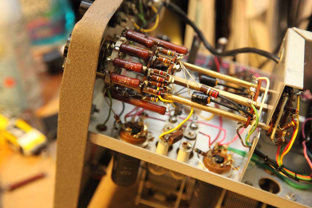
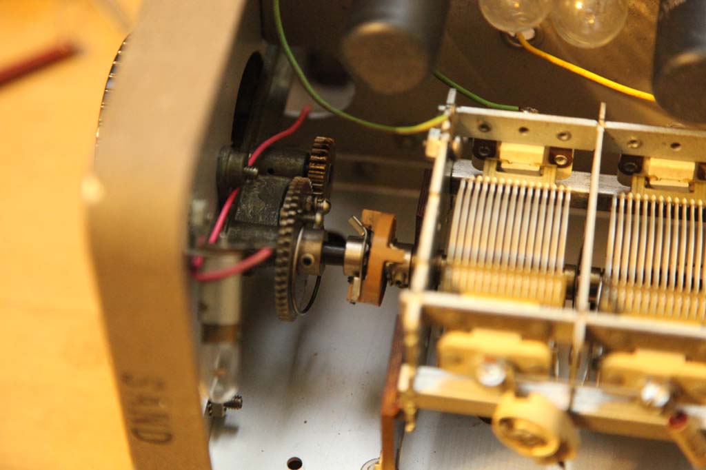
This last one shows the bent coupler. Hopefully will survive bending it back.
Posts: 16,533
Threads: 573
Joined: Oct 2011
City: Jackson
State, Province, Country: NJ
Reforming 1st cap....10uF 450V...they called them "long life" for a reason I guess, this one is 40uF measured 44uF.
Of course it is leaky and is getting better.
I only had a 130V Variac and a rectifier bridge and it is not enough, though I got 200-some volts out of it and brought it down to 13uA leak.
Reforming needs to be done close or at rated WV.
Then I realized I only need two diodes and two caps to make a doubler so I quickly (2 minutes) twisted together two caps and two 1N4007 and got me a doubler....right now working at 300V and can go to 380V which is closer to 450V than what was before.
Almost 400V of bare wires in front of me on the table.....nice!
Posts: 30
Threads: 0
Joined: Jun 2013
City: Las Vegas NV
If the coupler fails they are a fairly common item and shouldn't be hard to find.
keithw
Posts: 16,533
Threads: 573
Joined: Oct 2011
City: Jackson
State, Province, Country: NJ
Posts: 30
Threads: 0
Joined: Jun 2013
City: Las Vegas NV
https://www.fairradio.com would be a good place to start. Found some in their catalog.
keithw
Posts: 16,533
Threads: 573
Joined: Oct 2011
City: Jackson
State, Province, Country: NJ
Thanks Keith,
if I need it will give it a try.
Mike.
Posts: 16,533
Threads: 573
Joined: Oct 2011
City: Jackson
State, Province, Country: NJ
Hit a little snag, but maybe it is a blessing in disguise.
One cap had the base it twist-locked to broken (they twist-lock to an insulating base riveted to the chassis), and when I extracted it in order to reform the base went to pieces altogether (I was hoping to glue it back together).
Well, from the sch I realized the cap is a non-polar type (BTW the capacitance is still very close to the spec).
Thing is, a non-polar cap cannot be reformed.
So then I do not have to re-install it.
I bought just now the same (100uF 100V) non-polar and it will solder very well exactly where the wires that came to it come from. So....it is a non-issue, just have to get it in the mail.
I ordered from Parts Express. Shipping is low, I ordered 3, everything is about $7.50.
Posts: 16,533
Threads: 573
Joined: Oct 2011
City: Jackson
State, Province, Country: NJ
Well, Yesterday the cap came, I soldered it in.
Today checked all tubes, then checked the AC voltages, then DC voltages.
Then put the scope to the output.
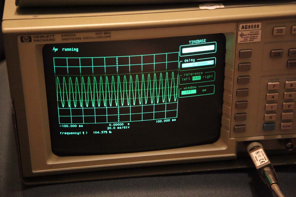
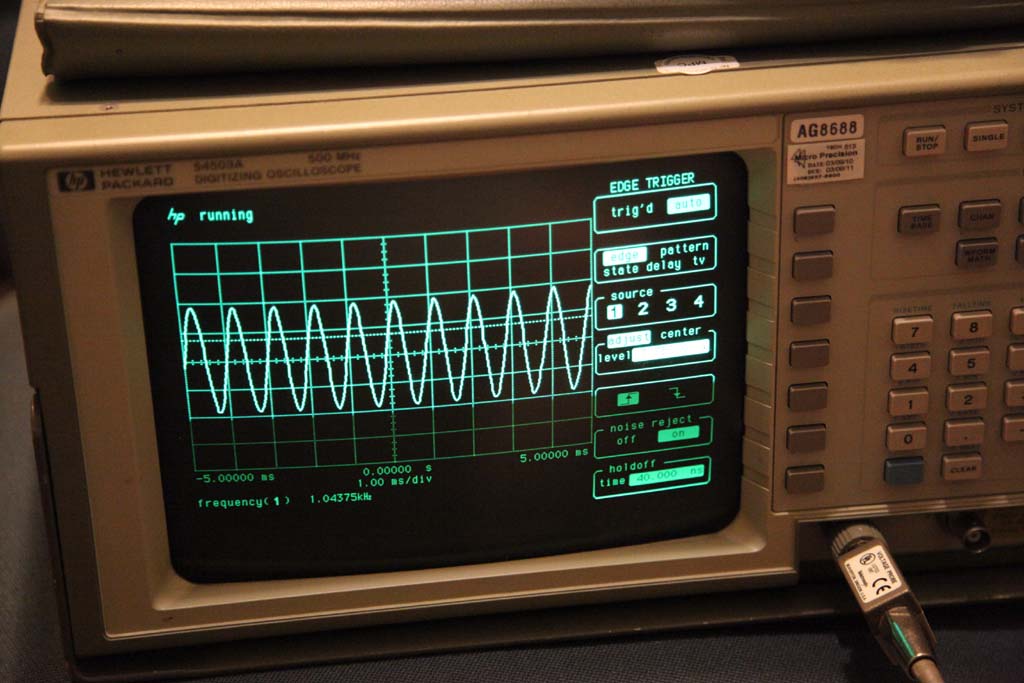
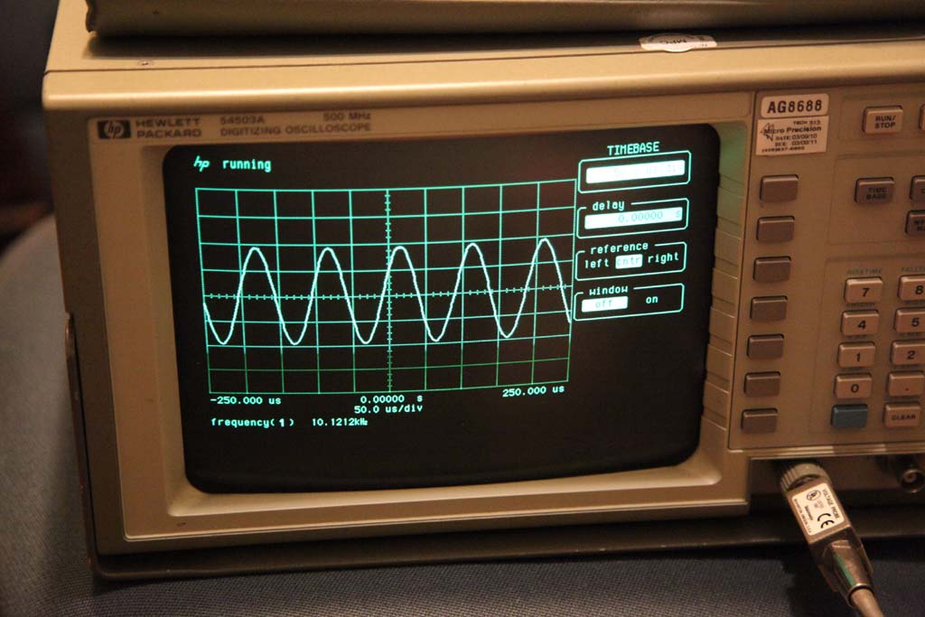
The stability of this thing is very good, as promised in Master Degree thesis of Bill Hewlett's. 
Here are some photos:
Notice the stability of the amplitude over the frequency range:
(Freq. reading could be seen on the scope at the bottom)
Front view
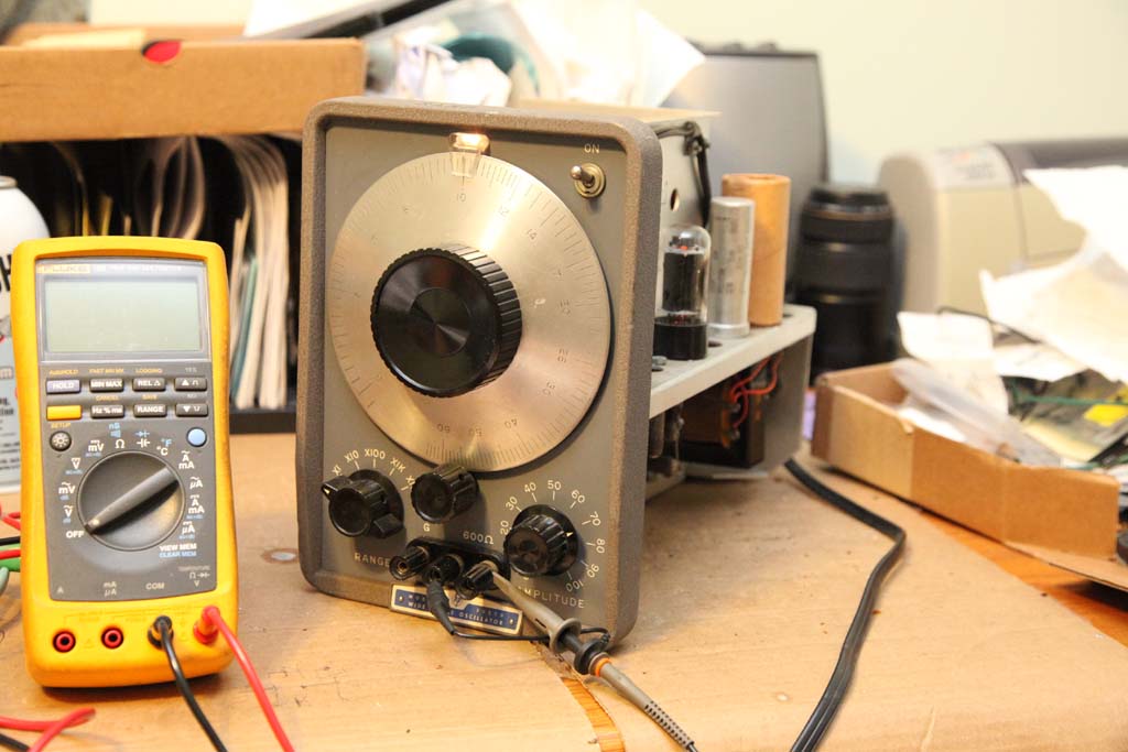
10 Hz
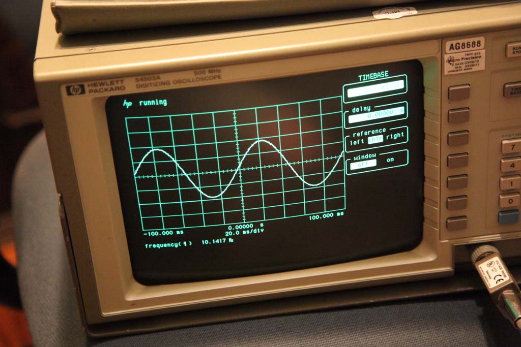
100 Hz
1kHz
10kHz
Users browsing this thread: 1 Guest(s)
|
|
Recent Posts
|
|
Philco newbie with P-1891-WA console questions
|
| Hello Jeff ,
Far as the Electrolytic capacitors go here is a list of parts.
that will work . I like using Nichicon and...radiorich — 09:50 PM |
|
Philco newbie with P-1891-WA console questions
|
| Well, I've been stumped at trying to get the first of 11 electrolytic capacitors. I got a schematic and have a list of t...Jeffcon — 07:54 PM |
|
Model 80 Antenna Issue?
|
| Thanks Gary and Rod.
I also found an article in the Philco Repair Bench under Service Hints and Tips, about installi...Hamilton — 12:32 PM |
|
Model 80 Antenna Issue?
|
| Hello Hamilton, here is a little information found in our Philco Radio Library at the bottom of the Home page. Hope it ...GarySP — 11:28 AM |
|
Model 80 Antenna Issue?
|
| I did as you suggested and touching the middle of the volume control did nothing so the coil has to be rewound. Any idea...Hamilton — 10:19 AM |
|
1949 Motorola 5A9M
|
| This would be the second portable in the "other radios" forum where I have a similar one in my collection. I h...Arran — 12:41 AM |
|
Looking for any info: 1977 Ford-Philco Console Hi-Fi Turntable and Radio
|
| Hi PittsburgTost.
The record changer looks like a Garrard or BSR (Likely Garrard). The spindles just pull out and pu...MrFixr55 — 11:57 PM |
|
Looking for any info: 1977 Ford-Philco Console Hi-Fi Turntable and Radio
|
| Hello PittsburghToast ,
Welcome aboard and it looks like gary may have something for you !
now if I dig through my se...radiorich — 11:35 PM |
|
Model 80 Antenna Issue?
|
| You are kind of on the right path. You can touch the grid cap of the Detector/Oscillator 36 tube. I'm expecting a respon...RodB — 08:48 PM |
|
Looking for any info: 1977 Ford-Philco Console Hi-Fi Turntable and Radio
|
| Welcome to the Phorum, PittsburghToast! I found an old thread that my interest you regarding the quality and worth of P...GarySP — 08:48 PM |
|
Who's Online
|
| There are currently no members online. |

|
 
|


![[-] [-]](https://philcoradio.com/phorum/images/bootbb/collapse.png)


