Posts: 13
Threads: 2
Joined: Feb 2014
City: Maine
Forum members,
I have a Philco model 38 Farm radio in restoration. I need to build a power supply for it to replace the batteries. I remember seeing some time ago a schematic that showed the circuit. I believe the circuit had connected several zeners to arrive at the various voltages needed. It was simple and clever. I started looking for the diodes, but lost the paper and with it the design. Has anybody in this forum built this before? I thought perhaps Ron Ramirez might remember. I think that it tapped +135vdc, +67.5vdc, +2vdc, -3vdc, and -7vdc. These are the listed source voltages for the 38, per the schematic. Otherwise, I'll need to breadboard something up and experiment.
St Tee
Posts: 16,533
Threads: 573
Joined: Oct 2011
City: Jackson
State, Province, Country: NJ
If using zeners I would use zeners with a wide range Iz. They should withstand the power equal Iz-max times Uz at about 14-15mA.
Then I would put two in them that are 68V in series, and in addition serialize a 3V and 7V zeners. Reference the point where the two connect to the lower 68V zener as a GND.
You will need a separate power source for 2V filaments. Could try AC, but filtered DC is cleaner.
Why 15mA?
Your B+ battery drain is 8-12mA and you need the zeners to withstand this current without load. The zeners should preferably still stabilize at about 2-3mA of current, which will be the case when the load is connected.
However Zeners are bad regulators to power up things - they are mostly used as references, so if you could make a clean DC power source, that would be better.
Again you need all voltages at low current except 2V (700mA).
Posts: 1,264
Threads: 32
Joined: Jan 2014
City: Wellborn Florida


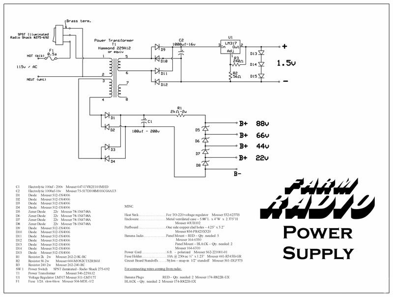
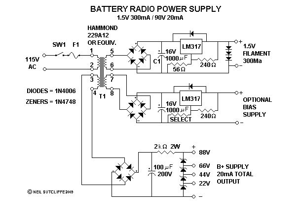
Hope this download thing works
Posts: 1,264
Threads: 32
Joined: Jan 2014
City: Wellborn Florida

Sorry about last post ! David
Posts: 4,905
Threads: 54
Joined: Sep 2008
City: Sandwick, BC, CA
One problem though, none of those designs supplies the 135 vdc you need. You don't really need Zener diodes in a B+ supply anyhow, those battery eliminators from the 1940s and 50s used a Pi filter like an AC/DC set and there was minimal hum or ripple with the right size electrolytics. If you used a filter choke, or a solid state substitute, there would be no ripple.
I have a schematic someplace from a Radio Craft magazine that uses an old style circuit where they supply the bias voltages through a resistor network in the B- through a resistor network. I may have it on file someplace as I sent it to Bob for his Philco 623 project. These days you can hook up diodes backwards to achieve the same result off of a cheap transformer.
Regards
Arran
Posts: 1,264
Threads: 32
Joined: Jan 2014
City: Wellborn Florida
I have never used the two design I posted placed here for your use. On the farm radio I have, use a D cell for the filments and 90 volts dc for the B+. The design was found on Phil's old radios look under building, what a nice site. To get 135 volts dc connect a full bridge rect to line voltage(120) add a 47UF cap and resistors to get the correct voltage for your current draw. Line voltage divided by .707 gives peak voltage which the Ecap will charge to without a bleeder resistor. I am sure the EEs will be alone to help explain what I am trying to say. David
Posts: 13,776
Threads: 580
Joined: Sep 2005
City: Ferdinand
State, Province, Country: Indiana
It's been many years since I built any power supplies such as what St Tee described, and like the ones David posted. I would have to search for my notes...and since I moved, I still don't know where some of my stuff is... 
--
Ron Ramirez
Ferdinand IN
Posts: 13
Threads: 2
Joined: Feb 2014
City: Maine
many years ago I looked at spice to do software simulation of circuit behavior . It 's a bit of overkill for this but there is open source software available that can model a circuit to see what components would work. It just might be a fun experiment. I am 25 years removed from this work but it's good to get back into the flow. BTW, the circuit I saw some time ago belonged to Ron, so it went beyond the napkin note phase as it was online somewhere.
Posts: 16,533
Threads: 573
Joined: Oct 2011
City: Jackson
State, Province, Country: NJ
Guys,
you do not need a simulator to do this kind of jobs.
Using Spice for this is, as we say, like using a cannon to shoot sparrows.
As for free Spice, LTSpice (fom Linear Tech) is a good tool and is fully free.
Posts: 13,776
Threads: 580
Joined: Sep 2005
City: Ferdinand
State, Province, Country: Indiana
St Tee Wrote:BTW, the circuit I saw some time ago belonged to Ron, so it went beyond the napkin note phase as it was online somewhere.
Yes, you did see it - and it was right here in the Phorum!
http://philcoradio.com/phorum/showthread.php?tid=469
(I had to do a Google search to find this. B-B-B-Bing didn't bring it up.)
--
Ron Ramirez
Ferdinand IN
Posts: 13
Threads: 2
Joined: Feb 2014
City: Maine
Posts: 13
Threads: 2
Joined: Feb 2014
City: Maine
To MORZH about using Spice: You're absolutely right. Started digging back in to it and realized that it was way too much. I then started drawing up a circuit when Ron gave us his reference. Thanks to all, and save the sparrows!
Users browsing this thread: 1 Guest(s)
|
|
Recent Posts
|
|
Philco 91 code 221
|
| Chassis grounds thru rivets is another good place to look. Oh and the stator screws on the tuning cap where the leads at...Radioroslyn — 08:11 AM |
|
Philco 91 code 221
|
| Dirty tube pins and socket, cold solder joint, stray tiny strand of wire, clean the entire area around the oscillator tu...RodB — 08:43 PM |
|
Philco 91 code 221
|
| I have been restoring one of these sets and switched it on yesterday. It didn't exactly spring into life, but after a co...Philconut — 08:26 PM |
|
Philco 50-925 antenna connections
|
| That's super. Glad to hear you figured it out. Paul.Paul Philco322 — 11:11 AM |
|
Philco 50-925 antenna connections
|
| Hello Keith,
great news !!
Sincerely Richardradiorich — 02:14 AM |
|
Philco 50-925 antenna connections
|
| Finally, got the antenna fixed (repaired some broken wires) and have the radio playing. I've got four different schemat...keith49vj3 — 09:38 PM |
|
1949 Motorola 5A9M
|
| Bob, Nice radio. I’ve not seen one before. Keep us updated!Joe Rossi — 07:56 PM |
|
Phioco 90 Power Transformer Wire Colors
|
| Thanks for adding that information.klondike98 — 06:09 PM |
|
Phioco 90 Power Transformer Wire Colors
|
| Although I have used this site as a resource for a number of years this is my first post. I am restoring a Model 90 si...vincer — 05:02 PM |
|
My collection presentation
|
| There is a complete instruction how to solve your problem. One piece of advice - be careful with the low-voltage capacit...Vlad95 — 09:32 AM |
|
Who's Online
|
There are currently 852 online users. [Complete List]
» 2 Member(s) | 850 Guest(s)
|
|
|

|
 
|


![[-] [-]](https://philcoradio.com/phorum/images/bootbb/collapse.png)


