06-03-2014, 07:40 PM
Found a nice, unmolested example of the 1934 cabinet design at the WARCI meet Sunday, and have a few questions with regards to the electronic restoration. First, for reference, here's a link to the PDF file schematic from Nostalgia Air. I've ordered "good" copies from Chuck: http://www.nostalgiaair.org/PagesByModel...013875.pdf
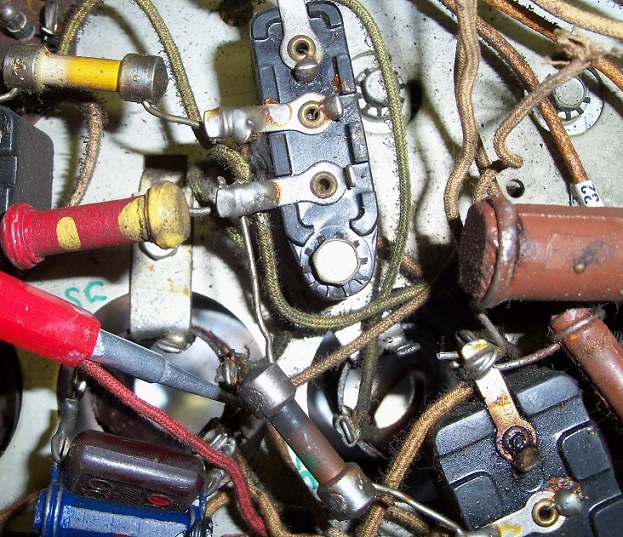
My first concern is this wire that is either cut or more likely broken off. It's attached to the OSC coil (I pointed to the lead the end of the wire is soldered to) You can see the broken end in the upper right hand corner of the pic:

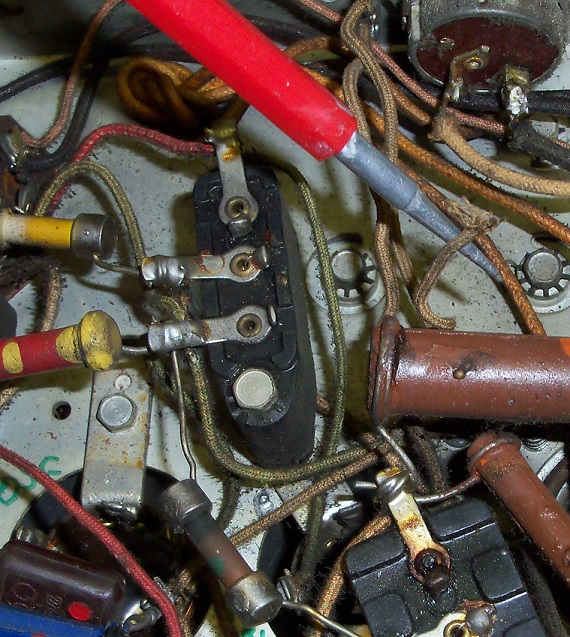
Here is the broken off end, which appears MAY have come from the off/on/volume control? :

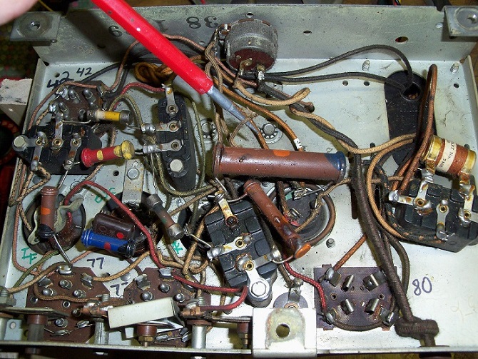
Here is a full view of the bottom of the chassis, pointing to the broken wire:

I'm hoping this set won't have the same OSC coil nightmares as the model 89's do. As with that set, if anyone has any info on the 84 as far as which terminals on the coil are the primary and secondary windings and (hopefully I won't need it) the number of turns of wire for each and direction to wind?
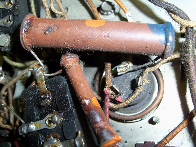
The other question concerns the electrolytic can containing an 8 mfd and a 10 mfd:

It appears to me that the terminal on top directly under the large resistor is the ground. There's green paint next to the terminal. Is that correct? Also, it appears to be a 'floating ground', as it's only grounded within the can itself, and not on the chassis (as there is a cardboard ring around the outside of the can). Is that the true ground, where everything on that terminal would be connected to the negative end of the replacement electrolytics?
Sorry for the dumb questions. Until I get a better, readable schematic, I'm at a loss, but I know there are some very knowledgeable and helpful Phorum members who I'm sure have tackled one of these small cathedrals at some point. Thanks!
My first concern is this wire that is either cut or more likely broken off. It's attached to the OSC coil (I pointed to the lead the end of the wire is soldered to) You can see the broken end in the upper right hand corner of the pic:
Here is the broken off end, which appears MAY have come from the off/on/volume control? :
Here is a full view of the bottom of the chassis, pointing to the broken wire:
I'm hoping this set won't have the same OSC coil nightmares as the model 89's do. As with that set, if anyone has any info on the 84 as far as which terminals on the coil are the primary and secondary windings and (hopefully I won't need it) the number of turns of wire for each and direction to wind?
The other question concerns the electrolytic can containing an 8 mfd and a 10 mfd:
It appears to me that the terminal on top directly under the large resistor is the ground. There's green paint next to the terminal. Is that correct? Also, it appears to be a 'floating ground', as it's only grounded within the can itself, and not on the chassis (as there is a cardboard ring around the outside of the can). Is that the true ground, where everything on that terminal would be connected to the negative end of the replacement electrolytics?
Sorry for the dumb questions. Until I get a better, readable schematic, I'm at a loss, but I know there are some very knowledgeable and helpful Phorum members who I'm sure have tackled one of these small cathedrals at some point. Thanks!
Greg V.
West Bend, WI
Member WARCI.org


![[-] [-]](https://philcoradio.com/phorum/images/bootbb/collapse.png)


