Philco Transitone 46-250 Code 125.
Posts: 16,533
Threads: 573
Joined: Oct 2011
City: Jackson
State, Province, Country: NJ
I bought this some 1-1/2 years ago during Kutztown auction.
Could not resist the $12 or so price (it was cheap).
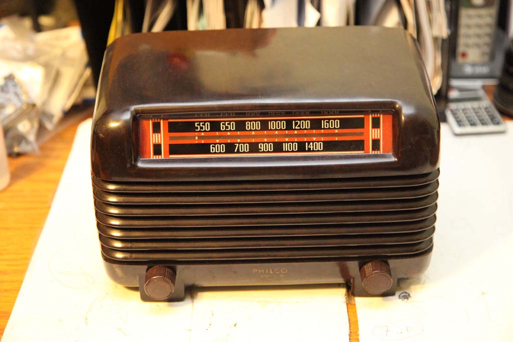
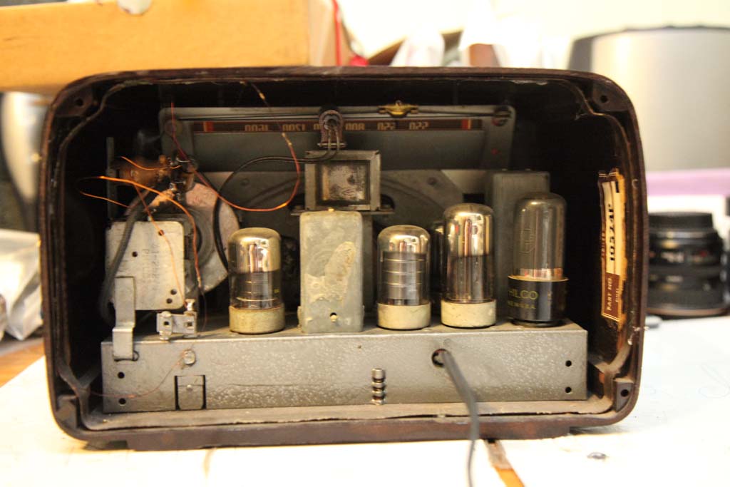
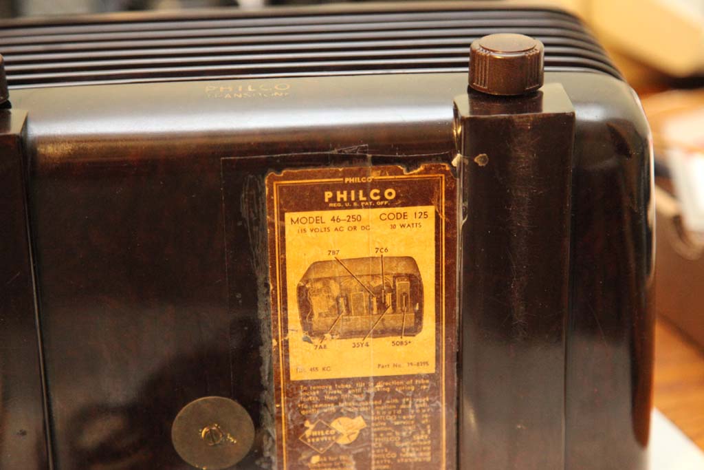
As you can see someone tended to it before - the chassis is hammer-painted.
The cabinet is just fine, the dial is like new (I do not think for 12 bucks I bought the radio with the new repro dial, but who knows).
Now, I am not tempted to turn it on even though somehow I think it might work.
I simply do not trust other unknown people with restorations.
Now having said that, I need some pointers as to how to extract the chassis.
I see one screw at the bottom, I see two screws holding the chassis behind the dial frame to the front, but the access is impeded by that very dial frame. Is there any trick or do I have to use some fine screw driver with partial access to the screw slot?
And of course I will have to unsolder the frame antenna.
It might be a short inspection and alignment, or...who knows.
Posts: 13,776
Threads: 580
Joined: Sep 2005
City: Ferdinand
State, Province, Country: Indiana
As I recall, the chassis should not be held inside with any screws on the dial frame. I just looked inside my 46-806 Tropic, which is the same size as a PT-2/46-250, to confirm. I've pulled these things out before and never saw anything holding the dial frame against the front of the cabinet.
1. Note where the two wires of the loop antenna connect. Take notes, take pictures, or both. Then unsolder these leads.
2. Remove knobs.
3. Remove screws from underneath - there should be 3 - one near the back, two very close to the front.
4. Carefully slide chassis out from back.
Voila. 
--
Ron Ramirez
Ferdinand IN
Posts: 16,533
Threads: 573
Joined: Oct 2011
City: Jackson
State, Province, Country: NJ
Ron
Thanks, I will shortly post pictures of the bottom and inside with screws.
Posts: 16,533
Threads: 573
Joined: Oct 2011
City: Jackson
State, Province, Country: NJ
One screw on the bottom.
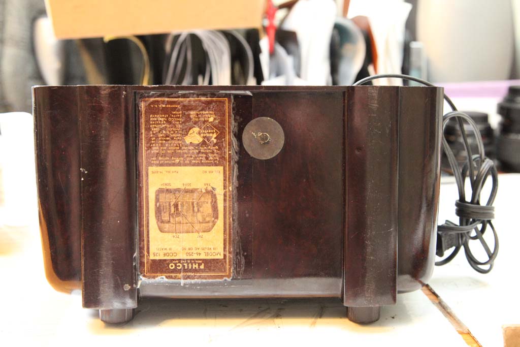
One screw at the right upper corner (look above the dial string roller)
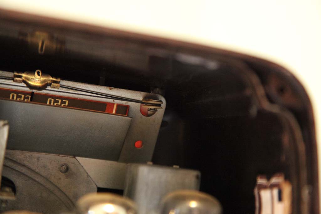
Same at the left upper corner.
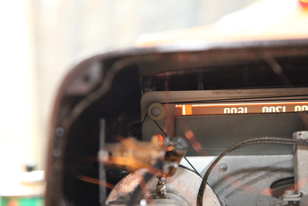
As you can see the vew of the screws is partial, and so is the access to them with scredriver.
Posts: 2,573
Threads: 337
Joined: Jun 2013
City: lawrenceville nj
mike
don`t over think it .screws should just hold dial plate in just remove one screw
Posts: 411
Threads: 42
Joined: Sep 2008
City: Ironton Ohio
I have the same radio, Dial glass does not come out with the chassis. There are 2 tabs on the front of the chassis that insert into 2 slots in the cabinet to hold the front of the chassis secure.
(This post was last modified: 09-01-2014, 03:11 PM by tab10672.)
Posts: 16,533
Threads: 573
Joined: Oct 2011
City: Jackson
State, Province, Country: NJ
So it one screw then and it will come out?
Posts: 411
Threads: 42
Joined: Sep 2008
City: Ironton Ohio
Yes, just the one screw, knobs and antenna. You will see after the chassis is out the 4 screws that hold the dial glass to the cabinet, 2 screws on each side held in by 2 thin metal retaining bars.
Posts: 16,533
Threads: 573
Joined: Oct 2011
City: Jackson
State, Province, Country: NJ
Posts: 16,533
Threads: 573
Joined: Oct 2011
City: Jackson
State, Province, Country: NJ
Well, did that.
Did not want to come out. Those tabs were seriously grabbed by their sockets.
I took a large flat screwdriver and raised each corner several times.
Eventually I dislodged the left corner, and then after 3 more minutes of harrassing it the right one.
The right has some white stuff iniside; I wonder if someone tried to glue it.
The chassis was repaired recently, with all caps replaced, lytics and film, with modern orange dip types.
The guy who did it obviously can solder, the rework is neat.
He left the antenna cap in a Philco tube, as it is on top and so is visible, it is probably restuffed as the tar is not what you see in originals, it is black and cracking a bit.
So, I will check it against the sch, and if it is OK, will try to power, and, should it work, give it the alignment.
Posts: 2,128
Threads: 18
Joined: Oct 2008
City: Merrick, Long Island, NY
Well, souhnds like you have a winner, perhaps a minor flaw, but power up slowly on variac to see.
Posts: 16,533
Threads: 573
Joined: Oct 2011
City: Jackson
State, Province, Country: NJ
Posts: 16,533
Threads: 573
Joined: Oct 2011
City: Jackson
State, Province, Country: NJ
One finding, the loop is not connected where it should.
That is, one side of it is, like it should, goes to tuning cap and Ctl grid of the mixer tube, but the other end is soldered to the external antenna lead connected to the antenna transformer, and not to the other transformer's coil's end. Which though makes the reception possible, disables AVC.
And the transformer seems fine.
PS. I only have code 121 sch whereas the chassis is code 125. Still I think this is wrong.
Posts: 16,533
Threads: 573
Joined: Oct 2011
City: Jackson
State, Province, Country: NJ
Found a couple of different prints both claiming being code 125.
One lists the rectifier 35Y4, Another - 35Z5, but the tube I have is 35Z3.
Checked the connection, seems to be correct for this tube.
The soldering on it is mostly neat, might be factory, the one that has been reworked is due to the caps change. So not sure if the tube is original or not.
The tube has no pilot lamp tap on the filament so the Candohm has a third pin (sch and photos of radios I see show 2-pin Candohm). The third pin is used to create that tap.
It clearly has been re-soldered. I think it is OK.
One sch that shows 35Z5 also shows 50L6 output tube (the one I have).
The sch showing 35Y4 shows 50B5 tube (the pins are different).
I think other than the antenna, the rest is fine.
Posts: 16,533
Threads: 573
Joined: Oct 2011
City: Jackson
State, Province, Country: NJ
Well, with the loop still disconnected I was able to receive my local station, so the radio is functional.
Now I will probably turn the chassis 180 degrees, connect the loop and try to align.
Which brings me to asking this:
1. in the alignment they are talking of connecting the meter "between the left hand terminal (high) and center terminal (low) of the chassis antenna terminal strip".
I do not have anything like this (you saw my photographs).
What is it that they connect to? Is there anything else other than antenna contacts on that strip (for those who have it)?
2. I think I will go usual way and connect to the speaker.
3. Not sure how to couple into the loop (I got no Hazeltine loop they refer to). Will probably use some coiled wire.
Users browsing this thread: 1 Guest(s)
|
|
Recent Posts
|
|
Model 80 Antenna Issue?
|
| Thanks Gary and Rod.
I also found an article in the Philco Repair Bench under Service Hints and Tips, about installi...Hamilton — 12:32 PM |
|
Model 80 Antenna Issue?
|
| Hello Hamilton, here is a little information found in our Philco Radio Library at the bottom of the Home page. Hope it ...GarySP — 11:28 AM |
|
Model 80 Antenna Issue?
|
| I did as you suggested and touching the middle of the volume control did nothing so the coil has to be rewound. Any idea...Hamilton — 10:19 AM |
|
1949 Motorola 5A9M
|
| This would be the second portable in the "other radios" forum where I have a similar one in my collection. I h...Arran — 12:41 AM |
|
Looking for any info: 1977 Ford-Philco Console Hi-Fi Turntable and Radio
|
| Hi PittsburgTost.
The record changer looks like a Garrard or BSR (Likely Garrard). The spindles just pull out and pu...MrFixr55 — 11:57 PM |
|
Looking for any info: 1977 Ford-Philco Console Hi-Fi Turntable and Radio
|
| Hello PittsburghToast ,
Welcome aboard and it looks like gary may have something for you !
now if I dig through my se...radiorich — 11:35 PM |
|
Model 80 Antenna Issue?
|
| You are kind of on the right path. You can touch the grid cap of the Detector/Oscillator 36 tube. I'm expecting a respon...RodB — 08:48 PM |
|
Looking for any info: 1977 Ford-Philco Console Hi-Fi Turntable and Radio
|
| Welcome to the Phorum, PittsburghToast! I found an old thread that my interest you regarding the quality and worth of P...GarySP — 08:48 PM |
|
Looking for any info: 1977 Ford-Philco Console Hi-Fi Turntable and Radio
|
| Welcome to the Phorum!
:wave:
We do not have anything on that unit in our digital library. There is a Sam's Photof...klondike98 — 08:47 PM |
|
Model 80 Antenna Issue?
|
|
I’ve replaced all the caps and resistors and the radio is working but minimal volume unless I put my hand near the re...Hamilton — 08:24 PM |
|
Who's Online
|
| There are currently no members online. |

|
 
|


![[-] [-]](https://philcoradio.com/phorum/images/bootbb/collapse.png)


