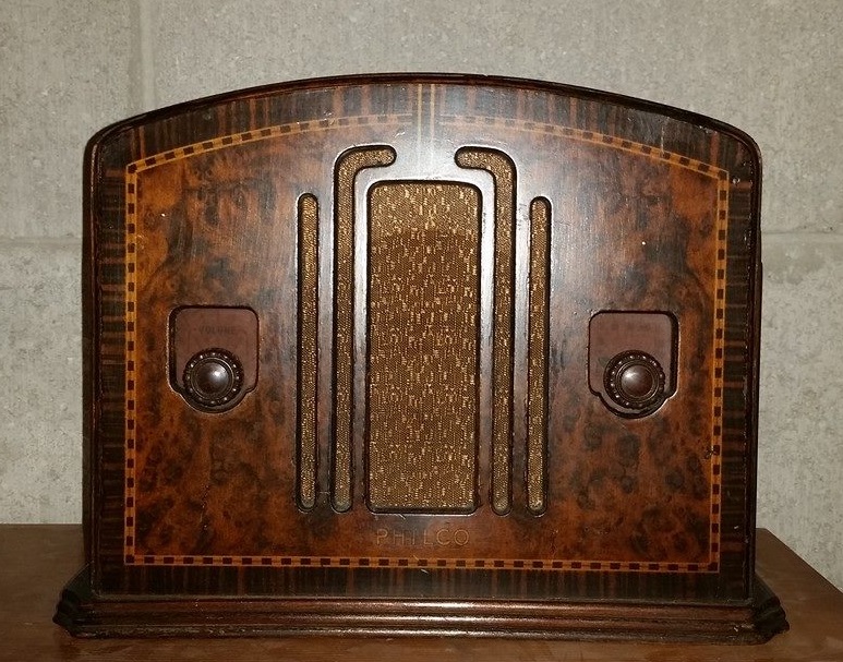
Next case - Odd Philco 42-720 Tropic
Posts: 4,930
Threads: 54
Joined: Sep 2008
City: Sandwick, BC, CA
Ron;
I think that the Hammond 270EX would be even better, the 5 volt winding is 3 amps and the 6.3 volt is 4 amps, the H.V winding is 144 ma. The question is, will it fit? The other may work but I don't know how close to 2 amps the 5 volt winding actually is since a 5Y3/5Y4/80 runs at a heater current of 2 amps, I would assume that 2 amps is the working current and not the max, the 6.3 volt winding is good enough on all transformers mentioned since all are rated for twice what the tube filaments draw, which is 1.55 amps.
Regards
Arran
Posts: 13,776
Threads: 580
Joined: Sep 2005
City: Ferdinand
State, Province, Country: Indiana
Thanks, Arran - I was leaning towards the 270EX anyway. It will fit.
--
Ron Ramirez
Ferdinand IN
Posts: 13,776
Threads: 580
Joined: Sep 2005
City: Ferdinand
State, Province, Country: Indiana
(11-13-2014, 02:58 PM)Ron Ramirez Wrote: The second time's the charm...maybe...(keeping my fingers crossed)
No, it wasn't:
[Image: http://www.philcoradio.com/images/phorum...e00028.jpg]
  
Perhaps the cold conditions of my house garage had a lot to do with it, but as you can see, none of the flocking fibers stuck to the metal. All that is left is Super 77 residue. Maybe Super 77 works in the summer, but it certainly does not do anything in the winter!
I will try again, only this time, I am going to follow the directions that came with the flocking fibers and use an acrylic paint as an adhesive (the "Apple Barrel Colors" widely available at craft stores and Wal-Mart). Which means I'll have to go get some as I do not have any (hmmm, I wonder if my wife might have some of that paint?) 
--
Ron Ramirez
Ferdinand IN
Posts: 118
Threads: 1
Joined: Nov 2014
City: Georgetown, IN
Follow directions? Nobody does does that! ;)
Great progress so far!
Posts: 244
Threads: 11
Joined: Oct 2011
City: Black Mountain, NC
Oh Flock......
Cossor 3468
GE 417A
Philco 118H
Radiola 17/100
Scott 800B6
Silvertone 6130
Stromberg 535M
Truetone D1952
Posts: 13,776
Threads: 580
Joined: Sep 2005
City: Ferdinand
State, Province, Country: Indiana
Hey, Jeremy! Great to see you here! 
PhilcoMike: X2.
[Image: http://www.philcoradio.com/images/phorum...e00029.jpg]
I give up. I can't do this in cold weather. Period, end of story. I can't go spraying fibers all over the basement, or upstairs.
Within 2 minutes of being out in the house garage, the acrylic paint (which should have remained wet for several minutes) began to act as if it were completely dry...because of the 34 degree temperature.
I've wasted enough time on this D**n thing. Time to move on to something else.
[Video: https://www.youtube.com/watch?v=_VrFV5r8cs0]
--
Ron Ramirez
Ferdinand IN
Posts: 1,533
Threads: 242
Joined: Sep 2012
City: West Bend, Wisconsin
Oh no! I'm sorry to see all of the trouble this has given you. If you want, send the back plate along with my 59C OSC coil when you finish with it and I'll be glad to reflock it for you. You were kind enough to help me out, and I'm happy to reciprocate  PM me if you'd like.
Greg V.
West Bend, WI
Member WARCI.org
Posts: 13,776
Threads: 580
Joined: Sep 2005
City: Ferdinand
State, Province, Country: Indiana
Greg: Wow, what can I say...PM forthcoming...
--
Ron Ramirez
Ferdinand IN
Posts: 13,776
Threads: 580
Joined: Sep 2005
City: Ferdinand
State, Province, Country: Indiana
Okay!
Since I last posted in this thread, I recapped my 53-960 - you can read about that here.
I have sent the 42-720's dial back plate off to Greg (NostalgiaRadioTime) to let him work his magic on it.
And now I have a new Hammond 270EX transformer.
It is longer than the original, plus it has wires protruding from both bells. The original had all of the wires coming from just one bell. So...that meant drilling and enlarging a second hole for some of the transformer leads.
Here's how it looks:
[Image: http://www.philcoradio.com/images/phorum...e00030.jpg]
[Image: http://www.philcoradio.com/images/phorum...e00031.jpg]
[Image: http://www.philcoradio.com/images/phorum...e00032.jpg]
I'm using only three screws to hold it onto the chassis; the fourth screw hole would be right above where the audio output transformer is mounted, so it could not be used.
I probably should have purchased the 270DX instead; that would have allowed me to reuse the original transformer bells. But this one has plenty of reserve current capacity and should never run hot. With all of that iron, it looks like a 25 cycle transformer (even though it isn't)!
This transformer has a 5 volt winding as well as a 6.3 volt winding, so I rewired the 6X5 tube socket to accept a 5Y3GT instead. The 5Y3GT is a more robust rectifier, and this mod should eliminate the possibility of a shorted rectifier tube.
--
Ron Ramirez
Ferdinand IN
Posts: 13,776
Threads: 580
Joined: Sep 2005
City: Ferdinand
State, Province, Country: Indiana
And It's Alive...
[Image: http://www.philcoradio.com/images/phorum...e00033.jpg]
I had a NOS GE 5Y3GT tube, so it went into the former 6X5 socket.
I crossed my fingers...plugged it in and turned it on...
In less than a minute, I was listening to my home SSTRAN playing 1950s music. 
I let it play for a half-hour or so, checking the transformer periodically. By the time I turned the radio off, the transformer was barely lukewarm, and I think a lot of that was due to the heat generated by the 5Y3GT and the two 7B5E audio output tubes, all of which are right behind the transformer.
So once the dial back plate returns and is reattached, this will only need an alignment and then should be good to go. I really won't be able to test SW until then. (Yes, I know I could now, but I don't want the dial cord to come completely unattached. You will note in the photos above that it is being held onto the flywheel with masking tape so it does not come off.)
--
Ron Ramirez
Ferdinand IN
Posts: 4,930
Threads: 54
Joined: Sep 2008
City: Sandwick, BC, CA
Ron;
How are the voltages reading out of that transformer? I was a bit concerned that the filament voltages may be a little high, I was not sure if you actually needed 3 amps current capacity for the 5 volt rectifier winding, as well as 4 amps would be overkill for the 6.3 volt winding since the rest of the tubes only draw 1.55 amps. Since the high voltage winding was already lower then the original, but at more then double the current rating, it should be pretty close to the 270-0-270 the radio calls for. If any are a little too high some wire wound resistors should take care of it.
It's not really a surprise that it's running cool, but one thing I don't like about the newer Hammond transformers are those plastic labels they glue on them rather then the nice brass badges they used to use, and the nylon washers they used on the bolts holding the end bells on, both are minor and easily undone.
Regards
Arran
(This post was last modified: 11-23-2014, 03:22 AM by Arran.)
Posts: 13,776
Threads: 580
Joined: Sep 2005
City: Ferdinand
State, Province, Country: Indiana
Arran
I went down and took some measurements.
6.3V is reading 6.54V.
5V is reading 5.13V.
I could not measure plate to plate on the rectifier as one of the electrolytic capacitors is in the way, so:
5Y3GT pin 6 to B- is reading 288.8 VAC.
B+ measured 325.3 VDC from rectifier output to B-; and 248.4 VDC from rectifier output to chassis ground.
This transformer has three terminals for AC input - common, 115 and 125. I am using the common and 125V taps. At least, that is what the diagram states (gray, 115V tap; black, 125V tap). I should measure with my ohmmeter (with the power off and radio unplugged, of course) to be sure I am using the 125V tap and not the 115V tap.
AC line input is reading 123.9V.
Using a 5Y3GT, I only needed 2A for the 5V winding. And using LEDs for the three pilot lamps will cut down on current consumption a little bit.
--
Ron Ramirez
Ferdinand IN
Posts: 4,930
Threads: 54
Joined: Sep 2008
City: Sandwick, BC, CA
Ron;
Current won't be an issue with the transformer, however the filament voltages, or even the plates running a bit high may shorten the life of the tubes somewhat. You can use regular #44 lamps for the pilot lamps, if anything it will drop the filament voltages down some more and not harm the transformer.
Regards
Arran
Posts: 1,533
Threads: 242
Joined: Sep 2012
City: West Bend, Wisconsin
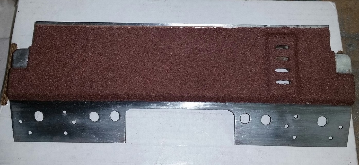
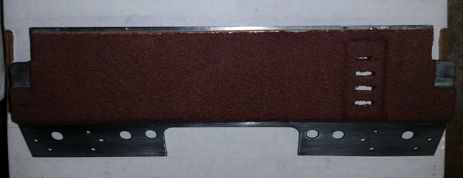
Since it was such a snowy, cold, icy, miserable weather evening here in southeastern, Wisconsin, I had a bit of time after work to give Ron's dial back plate some attention. I think I had some success! 


And I also managed to install the freshly rewound OSC coil, courtesy of Ron, into my 59C, and...
It's alive!!
I was able to tune in WBBM in Chicago, some 120 miles south of here.

So in spite of the weather, it was a good day!
Greg V.
West Bend, WI
Member WARCI.org
Posts: 13,776
Threads: 580
Joined: Sep 2005
City: Ferdinand
State, Province, Country: Indiana
W O W   
Man, that dial back plate is now beautiful. It looks like it was just freshly flocked at the Philco factory! (try saying that three times)
My hat's off to you, Greg. I don't know how you did it...but I am certainly glad that you did! Thank you so much for your help, I really appreciate it.
I'm guessing you must be doing this in a heated room. I simply could not make things work right in the cold house garage. I think that if I ever attempted it again, I would work outdoors in hot weather, treating it just as I would refinishing a radio cabinet.
I am also glad to see that your 59C is up and running, too. 
Greg, thank you again! So now I will only need to align the radio and the chassis will be done. That will leave cabinet cosmetics...that will have to wait for warmer weather.
--
Ron Ramirez
Ferdinand IN
Users browsing this thread: 1 Guest(s)
|
|
Recent Posts
|
|
[split] New member...
|
| You may have to start further back with your signal injection at the IF signal grid, then tune the second IF transformer...RodB — 10:28 AM |
|
[split] New member...
|
| Well, with the replacement tuning assembly, I have finally put the unit back together and aligned the dial. The first s...HowardWoodard — 01:01 AM |
|
Philco Model 16 wiring question
|
| Well, finding a short is easy.
Like I said, disconnect the transformer's secondary windings and see if it persists.
If...morzh — 09:48 PM |
|
Restoring Philco 96
|
| Nice one!Stan the Man — 09:37 PM |
|
Restoring Philco 96
|
| I have eventually replaced the speaker and shot the video, which only shows the upper part of the dial as the hum is ver...morzh — 09:24 PM |
|
Rogers Majestic R-646
|
| Kinda weird to see both open
Nothing weird if you remember that this radio is about 100 years old :)Vlad95 — 07:49 PM |
|
Philco 42-345 Restoration/Repair
|
| I believe I'm making progress, resistors have been rechecked and corrected, removed that ugly blue capacitor and more wi...osanders0311 — 07:38 PM |
|
Philco Model 16 wiring question
|
| Thanks Morzh
Yes I recapped everything and replaced almost all the resistors as well. I redid #99 with .015 safety ca...bobclausen — 07:11 PM |
|
Philco Model 16 wiring question
|
| Well...pull out every single load of the transformer. For every winding.
Unsolder if needed.
Then re-do your dim bulb....morzh — 07:02 PM |
|
Rogers Majestic R-646
|
| Kinda weird to see both open, but once you get it up and running, really pay attention to your sound. Listen for loud cr...TV MAN — 06:59 PM |
|
Who's Online
|
| There are currently no members online. |

|
 
|


![[-] [-]](https://philcoradio.com/phorum/images/bootbb/collapse.png)


