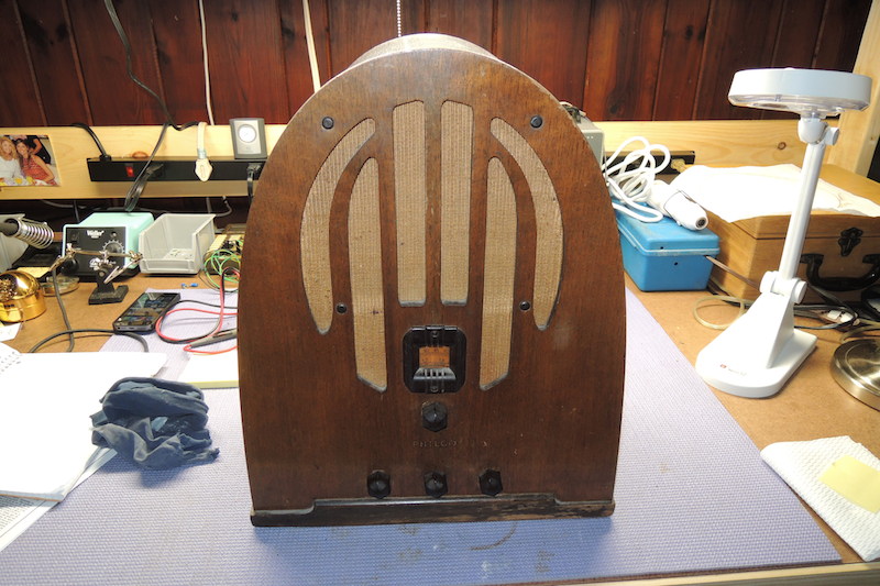
New to Phorum and a Philco 38
Posts: 18
Threads: 3
Joined: Nov 2014
City: Groveland MA
Hello all, I just registered to the Phorum tonight, after the purchase of a Philco 38. The radio had been converted to AC at one point, then sometime after that the transformer failed. The previous owner then removed the TX with the thought of replacing it but never did.
So, my challenge is to restore it back to being a battery set as it should be. This is only my second Philco, my first being a Hippo. I really like the styling of this set, and look forward to getting it going.
I suspect that I will need to post questions in the future as I begin this project. I'll take some photos and post them also.
Russ
Posts: 2,573
Threads: 337
Joined: Jun 2013
City: lawrenceville nj
radioalfa
welcome to the philco phorum
sam
Posts: 4,906
Threads: 54
Joined: Sep 2008
City: Sandwick, BC, CA
Hopefully the previous conversion attempt did not butcher the chassis too badly, which is often the case when someone tries to convert a battery set into an AC set. The styling is very much like a Philco 60B, which has five tubes but one is a #80 rectifier, it looks like the model 38 used a type #15, a #32, a #32, a #30, and a #19, so probably about the same performance wise in the front end, although the #19 output will probably make it sound pretty good.
Regards
Arran
(This post was last modified: 11-23-2014, 05:24 AM by Arran.)
Posts: 7,303
Threads: 269
Joined: Dec 2009
City: Roslyn Pa
Hi Russ and welcome to the Phorum!!
I've always liked farm sets, something about being off the grid or the grid is nowhere near you. The original owner probably spent many nights listening to this set without an electric light just him and a kerosene lamp. Shadows all around odd noises kinda spooky! In 1935 lots of good shows on the airwaves Fibber McGee & Molly was just starting out while Amos & Andy, The Shadow, and Calling all Cars had been well established by then.
Hopefully someone here has a 38 chassis that can be seen so you can have something to go by other than just the diagram. Sometimes the parts placement can be a little critical so some pics can really help. Sorry I don't have a 38.
Best of luck w/it
Terry
Posts: 16,533
Threads: 573
Joined: Oct 2011
City: Jackson
State, Province, Country: NJ
Good thing about going back to battery set is you don't need no stinkin' transformer, or ballasts.
You connect all the filaments together, remove the rectifier and toss the bad power transformer, then wire the battery cable back which is also pretty straightforward.
Posts: 5,182
Threads: 276
Joined: Nov 2012
City: Wilsonville
State, Province, Country: OR
Posts: 18
Threads: 3
Joined: Nov 2014
City: Groveland MA
Hi pholks, thanks for the welcome, tips,and encouragement. As I mentioned I will get some photos soon, hopefully later tonight.
Russ
Posts: 18
Threads: 3
Joined: Nov 2014
City: Groveland MA
I have had some time to look at the 38 more closely, here is what I know so far;
As I mentioned above, a conversion had been done to allow the radio to operate on AC, but the transformer failed and the previous owner removed it.
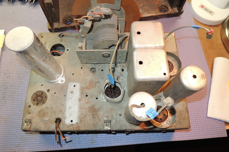
Two tube sockets have been removed, type 6 and type 30.
Other tubes
Type 19 replaced with a tube with no markings
Type 15 replaced with 6A8 G
Type 32 replaced with 75
Type 32 replaced with 78
With the exception of type 19, all other tube sockets have been replaced.
A multi section electrolytic has been added
Holes have been drilled for TX, along with some other miscellaneous holes
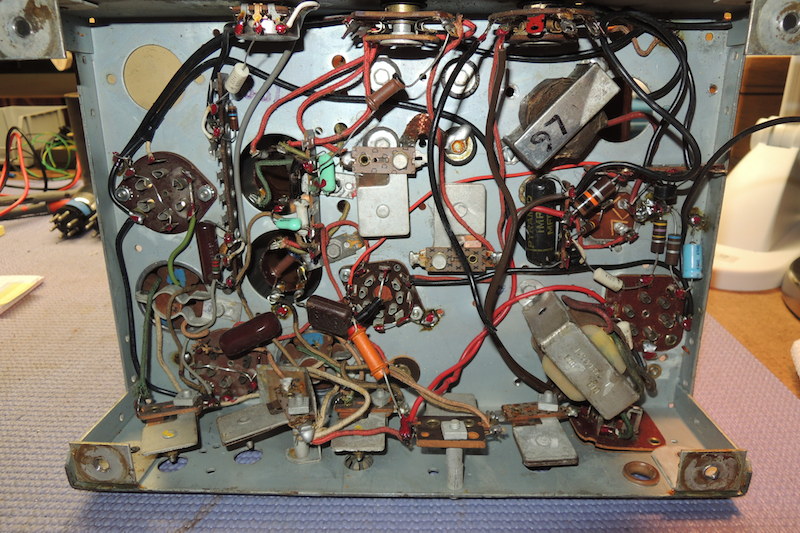
Has "newer" wire and some caps
I have some pictures, and will set up an account online so they can be viewed in the next couple of days.
Russ
Posts: 4,906
Threads: 54
Joined: Sep 2008
City: Sandwick, BC, CA
The #19 uses a six pin base, so they may have used a #41 or #42 in it's place. The #30 has a four pin base, as does the two #32 tubes, if there was a type 6 tube in your set that was a four pin ballast, which means the set was actually a 38A. The type #15 had a five pin base, the 6A8G is obviously an octal. So yes, there was some butchery that went on with this set.
Regards
Arran
Posts: 18
Threads: 3
Joined: Nov 2014
City: Groveland MA
Here are a few photos of the 38.


Russ
Posts: 4,906
Threads: 54
Joined: Sep 2008
City: Sandwick, BC, CA
Thankfully the IF cans and front end coils still seem to be in place, along with all the trimmers and padders, and the tube shield bases, unfortunately they pulled out all of the Bakelite block condensers and added a bunch of stuff that the model 38 would never have had. It looks like this was indeed a model 38 and not a 38A as there is a hole for a ballast socket but no evidence that a socket was ever installed. I really hate it when people attempt to convert battery operated radios into AC sets by installing AC tubes, it almost never works out well, and all they accomplish is to take an all original set with at least some historical value and make it into a parts set. It's so much less effort to rebuild a battery set as is, and then build an off board AC operated power supply to supply the correct voltages.
Regards
Arran
(This post was last modified: 11-26-2014, 02:01 AM by Arran.)
Posts: 18
Threads: 3
Joined: Nov 2014
City: Groveland MA
Hi Arran, thanks for your reply. I agree also, it is much better to use a battery eliminator for a DC set than to convert it to AC.
It looks like the type 6 ballast tube socket was there, I can see that the rivets were ground out. If I am understanding things, a 38 would have had the socket, but a jumper would have been placed across the filament contacts. Does that sound right?
Given what you see here, do you think a restoration back to DC is reasonable?
I think my first plan should be to use the schematic to create a point to point wiring diagram, and secondly to see if I can even locate the proper sockets.
Russ
Posts: 13,776
Threads: 580
Joined: Sep 2005
City: Ferdinand
State, Province, Country: Indiana
(11-26-2014, 09:15 AM)radioalfa Wrote: It looks like the type 6 ballast tube socket was there, I can see that the rivets were ground out. If I am understanding things, a 38 would have had the socket, but a jumper would have been placed across the filament contacts. Does that sound right?
That is correct. I've owned a few model 38 sets over the years; all of them had the socket for the #6 ballast, but all had a removable heavy jumper wire across the filament pins of that socket. The stickers on the back of the chassis indicated "CHASSIS TYPE 38" and not "38A".
--
Ron Ramirez
Ferdinand IN
Users browsing this thread: 1 Guest(s)
|
|
Recent Posts
|
|
1949 Motorola 5A9M
|
| This would be the second portable in the "other radios" forum where I have a similar one in my collection. I h...Arran — 12:41 AM |
|
Looking for any info: 1977 Ford-Philco Console Hi-Fi Turntable and Radio
|
| Hi PittsburgTost.
The record changer looks like a Garrard or BSR (Likely Garrard). The spindles just pull out and pu...MrFixr55 — 11:57 PM |
|
Looking for any info: 1977 Ford-Philco Console Hi-Fi Turntable and Radio
|
| Hello PittsburghToast ,
Welcome aboard and it looks like gary may have something for you !
now if I dig through my se...radiorich — 11:35 PM |
|
Model 80 Antenna Issue?
|
| You are kind of on the right path. You can touch the grid cap of the Detector/Oscillator 36 tube. I'm expecting a respon...RodB — 08:48 PM |
|
Looking for any info: 1977 Ford-Philco Console Hi-Fi Turntable and Radio
|
| Welcome to the Phorum, PittsburghToast! I found an old thread that my interest you regarding the quality and worth of P...GarySP — 08:48 PM |
|
Looking for any info: 1977 Ford-Philco Console Hi-Fi Turntable and Radio
|
| Welcome to the Phorum!
:wave:
We do not have anything on that unit in our digital library. There is a Sam's Photof...klondike98 — 08:47 PM |
|
Model 80 Antenna Issue?
|
|
I’ve replaced all the caps and resistors and the radio is working but minimal volume unless I put my hand near the re...Hamilton — 08:24 PM |
|
Looking for any info: 1977 Ford-Philco Console Hi-Fi Turntable and Radio
|
| Hi there! this is my first time posting. I recently picked up this Ford-Philco Console record player and radio at a yard...PittsburghToast — 07:28 PM |
|
philco predicta
|
| I found that where I have the 140v B+ there is 50v and the tuner receives 235v through the orange cablecgl18 — 04:14 PM |
|
Philco 91 code 221
|
| Chassis grounds thru rivets is another good place to look. Oh and the stator screws on the tuning cap where the leads at...Radioroslyn — 08:11 AM |
|
Who's Online
|
| There are currently no members online. |

|
 
|


![[-] [-]](https://philcoradio.com/phorum/images/bootbb/collapse.png)


