Posts: 2,037
Threads: 367
Joined: Jun 2010
City: Dover, OH
No matter where you go, there you are.
(This post was last modified: 01-30-2015, 04:33 PM by Jayce.)
Posts: 3,160
Threads: 59
Joined: Apr 2011
City: Lexington, KY
John KK4ZLF
Lexington, KY
"illegitimis non carborundum"
Posts: 2,037
Threads: 367
Joined: Jun 2010
City: Dover, OH
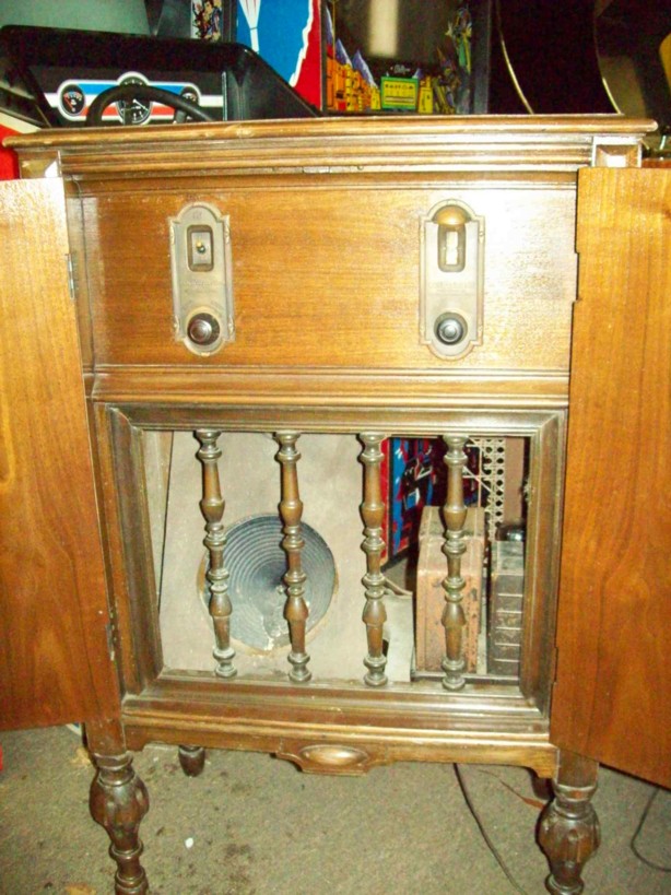
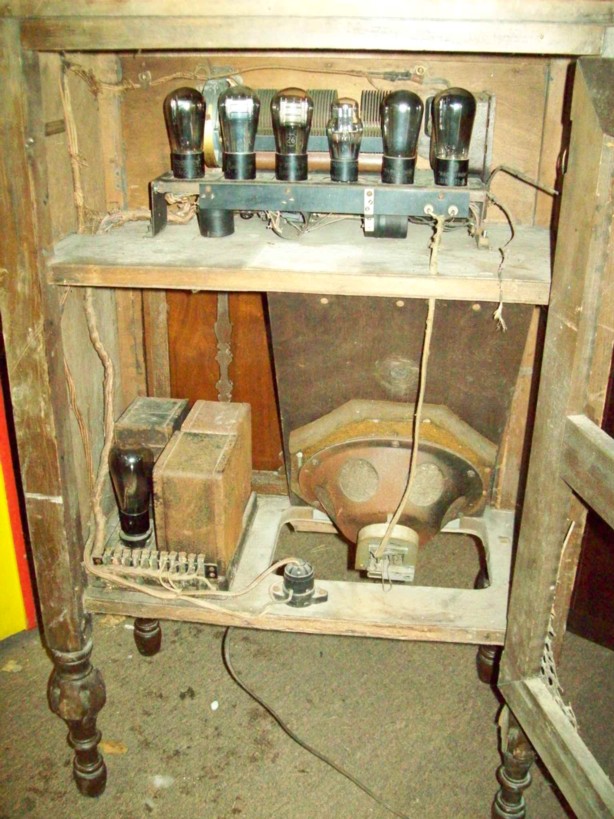
It's quite a price jump from the basic model 17, which cost $130!  No wonder they only sold around 3000 of the model 50. In fact, I could have had three model 17's for $90 a while back, with some tubes! Sadly, they were all missing the dial light hoods.
An article I read on that same site says the Radiola 17 was RCA's first true AC radio. Would that make the 50 their first true AC console? Being from 1927-28, these along with my Radiola 33 do seem to be the earliest all AC radios I have seen. Yes there were models like the Radiola 30-30A, but those were more like a hybrid of battery set combined with an amp/battery eliminator chassis.
No matter where you go, there you are.
Posts: 4,106
Threads: 310
Joined: Nov 2013
City: Kings Park NY
Ummmmmmmmm, Is that ATARI Pole Position???
I think it is and I want to come play it, 
Kirk
Times I have been electrocuted in 2021
As of 1/01/2021
AC: 4 DC: 1
Last year: 6
Posts: 467
Threads: 31
Joined: Sep 2009
City: Lapeer
State, Province, Country: MI
Great find! 
Joe
Matthew 16:26 "For what does it profit a man if he gain the whole world, yet lose his own soul?"
Posts: 2,037
Threads: 367
Joined: Jun 2010
City: Dover, OH
(02-02-2015, 07:15 PM)OldRestorer Wrote: Ummmmmmmmm, Is that ATARI Pole Position???
I think it is and I want to come play it, 
Kirk
Why yes, that is an ATARI Pole Position. In fact, it is a Pole Position 2! Needs the monitor recapped though... Took two machines to get enough parts and a decent cabinet to make one. So far, $140 invested, which is cheap for Pole Position! These things can be nightmares!
No matter where you go, there you are.
Posts: 395
Threads: 33
Joined: Jul 2013
City: Horsham, PA
Jayce,
I'd love to see a picture of the underside of that chassis. Is it all original under there?
Posts: 2,037
Threads: 367
Joined: Jun 2010
City: Dover, OH
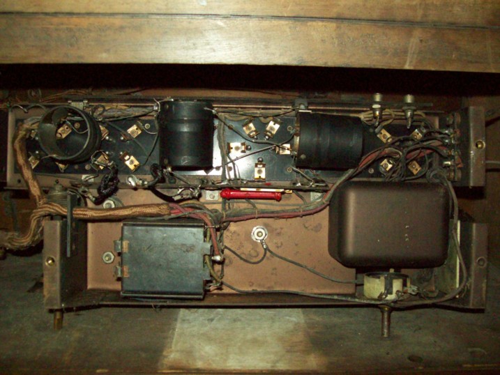
Both chassis look untouched as far as I can tell. First, here is the IF chassis. Pretty simple underneath except for what looks like a capacitor can.

Next is the power supply. Three Rheostats? (Am I spelling that righ?) I knew there was one which seemed to act as a hum control, but three? What do they do? Nothing on the schematic I found mentions these, but it appears this is the way the 17 was built. All three are adjustable from the top, though you need a long shanked, skinny screw driver to reach the one.

No matter where you go, there you are.
Users browsing this thread:
|
|
Recent Posts
|
|
Philco 42-345 Restoration/Repair
|
| Hi, there's a lot to consider when designing these circuits so you shouldn't have a lot of concern when replacing caps. ...RodB — 02:03 PM |
|
Philco 42-345 Restoration/Repair
|
| I have ordered and received new caps for this radio and hope I've ordered the correct ones. I tried matching them to the...osanders0311 — 11:35 AM |
|
Philco newbie with P-1891-WA console questions
|
| Hello Jeff ,
Far as the Electrolytic capacitors go here is a list of parts.
that will work . I like using Nichicon and...radiorich — 09:50 PM |
|
Philco newbie with P-1891-WA console questions
|
| Well, I've been stumped at trying to get the first of 11 electrolytic capacitors. I got a schematic and have a list of t...Jeffcon — 07:54 PM |
|
Model 80 Antenna Issue?
|
| Thanks Gary and Rod.
I also found an article in the Philco Repair Bench under Service Hints and Tips, about installi...Hamilton — 12:32 PM |
|
Model 80 Antenna Issue?
|
| Hello Hamilton, here is a little information found in our Philco Radio Library at the bottom of the Home page. Hope it ...GarySP — 11:28 AM |
|
Model 80 Antenna Issue?
|
| I did as you suggested and touching the middle of the volume control did nothing so the coil has to be rewound. Any idea...Hamilton — 10:19 AM |
|
1949 Motorola 5A9M
|
| This would be the second portable in the "other radios" forum where I have a similar one in my collection. I h...Arran — 12:41 AM |
|
Looking for any info: 1977 Ford-Philco Console Hi-Fi Turntable and Radio
|
| Hi PittsburgTost.
The record changer looks like a Garrard or BSR (Likely Garrard). The spindles just pull out and pu...MrFixr55 — 11:57 PM |
|
Looking for any info: 1977 Ford-Philco Console Hi-Fi Turntable and Radio
|
| Hello PittsburghToast ,
Welcome aboard and it looks like gary may have something for you !
now if I dig through my se...radiorich — 11:35 PM |
|
Who's Online
|
There are currently 1115 online users. [Complete List]
» 2 Member(s) | 1113 Guest(s)
|
|
|

|
 
|


![[-] [-]](https://philcoradio.com/phorum/images/bootbb/collapse.png)


