Airline Movie Dial model 62-309 - FINISHED!
Posts: 1,531
Threads: 242
Joined: Sep 2012
City: West Bend, Wisconsin
Oh boy.
I seem to have a knack for finding majorly "modified" sets. So I'm hoping some of the phine phorum members who are a lot more knowledgeable on un-modifiying other's ideas back to schematic correct can give me some much needed guidance. Perhaps my savior on many occasions previously, Terry, can have a look.
First here is the schematic:
http://www.nostalgiaair.org/Resources/435/M0011435.htm
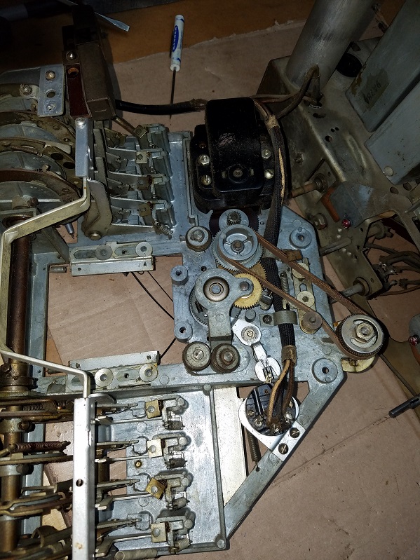
I'll start with an "easy" question....the tuning knob does not move the tuning capacitor or the movie dial drum manually. It's froze. There is an electric motor for tuning and I'm wondering if the set needs to be under power and the motor running for the tuning mechanism to function, either manually or with electrical assist?
Now the fun part...someone was trying to convert this to some type of push-pull configuration and added two extra speakers and an extra audio output transformer. AND...added an extra tube! A 6SC7...
1.) A 6L6 was subbed for the 6F6. My tube substitution manual doesn't list a 6L6 as a substitute. Are they compatible?
2.) An extra RCA jack was added with two slide off/on switches attached to it. It says "TV or FM" and then below it "Phono". Now there already was a factory RCA jack for phono on the back of the chassis. Should this just be cut out and eliminated? :
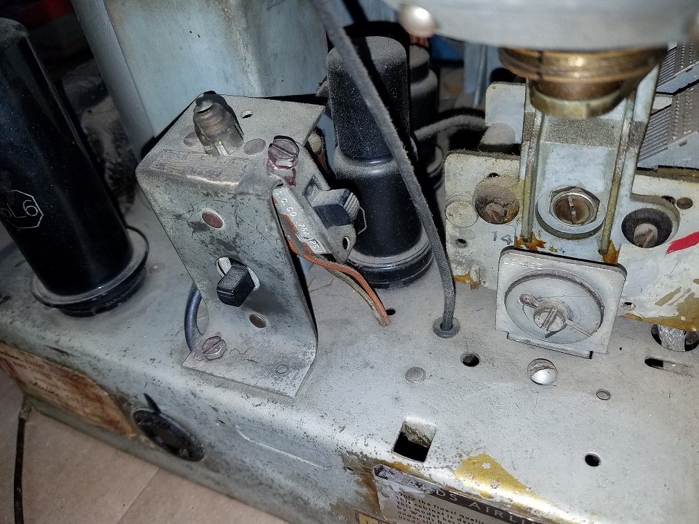
3.) Here's the extra audio output transformer mounted on top of the chassis, top and bottom view. I assume this was added to power two extra speakers mounted below the main speaker?
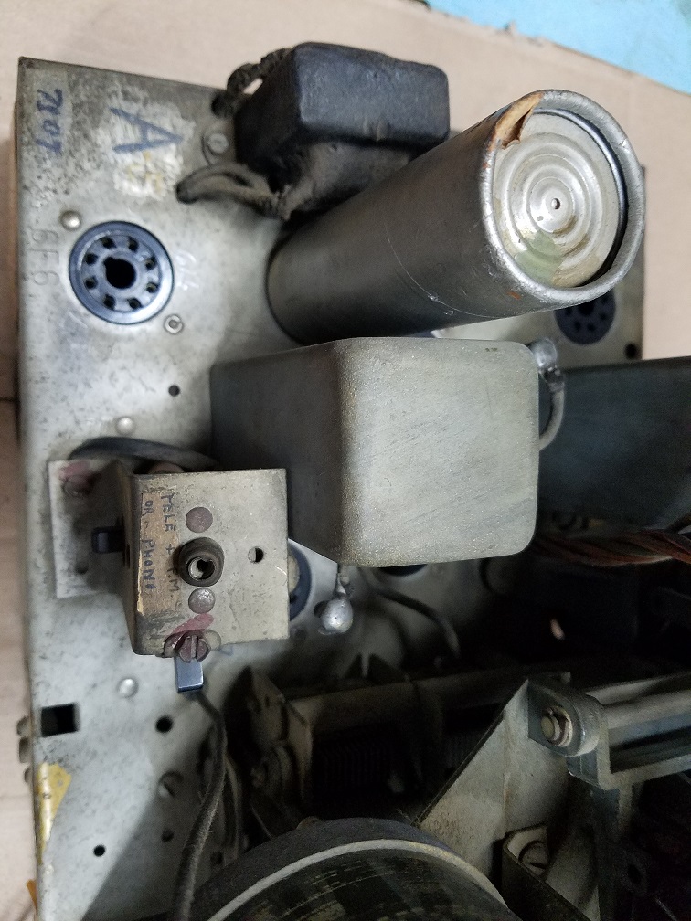
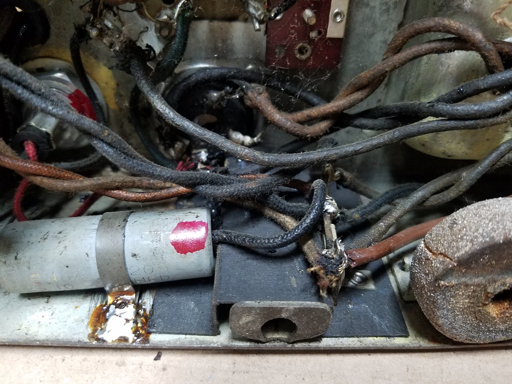
4.) Here is the extra added 6SC7 tube top and bottom. This looks to be a total mess and how is the best way to eliminate this?
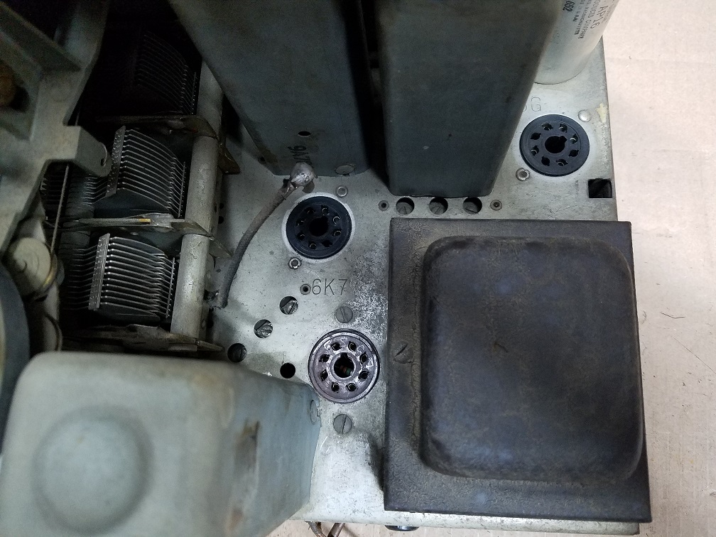
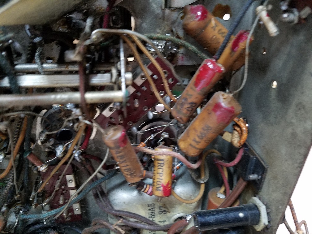
More to come....
Greg V.
West Bend, WI
Member WARCI.org
Posts: 1,531
Threads: 242
Joined: Sep 2012
City: West Bend, Wisconsin
Another view of the added tube:
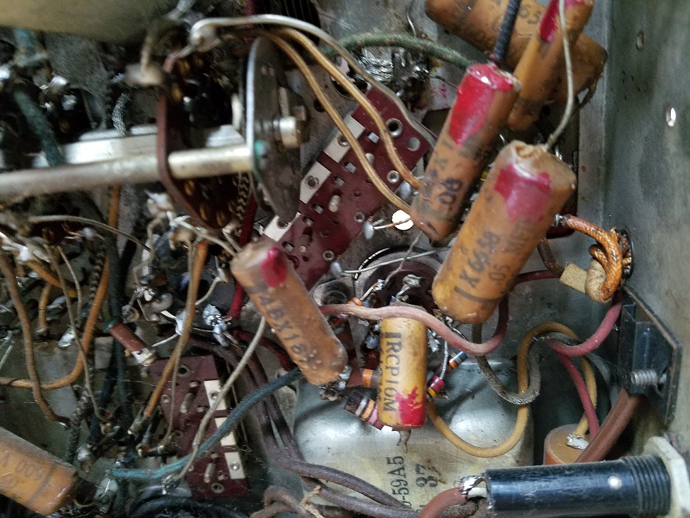
And the speaker board with extra two speakers added:
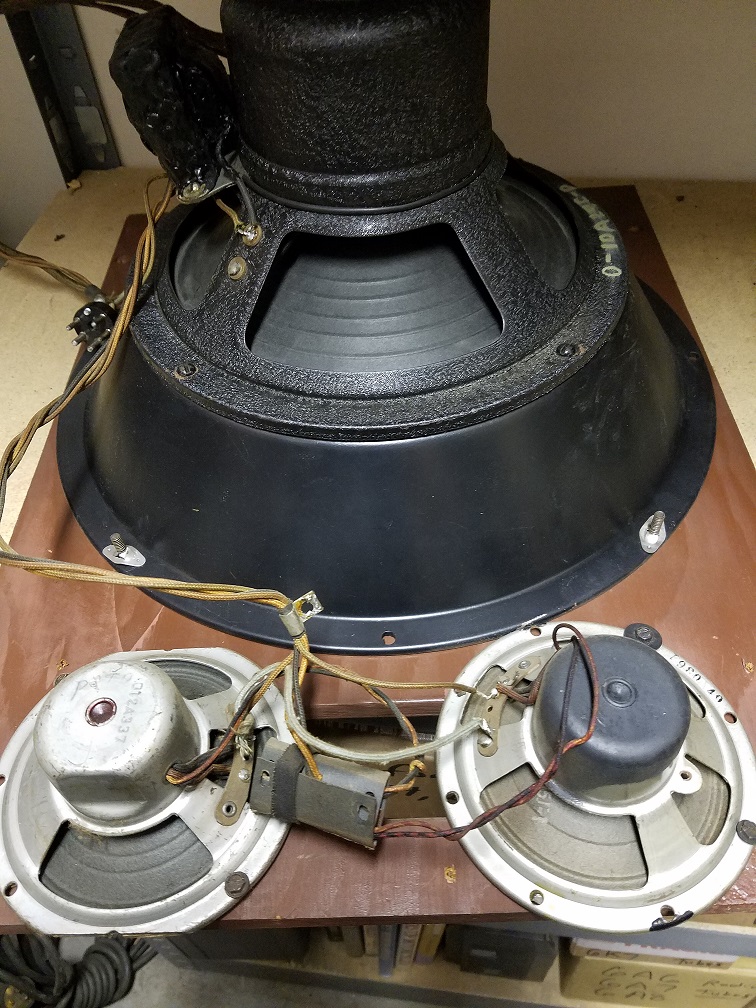
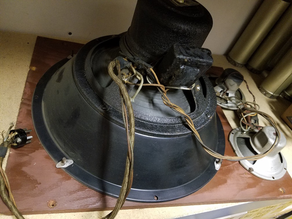
Some acoustic tubes were added and the bottom of the cabinet was enclosed These can be easily eliminated but I just wanted to show to the extreme this old audiophile went to in his efforts to try to get more power and gain out of this set:
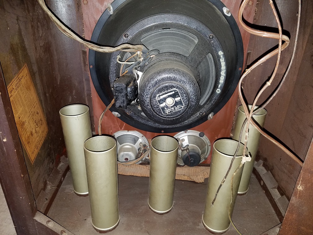
If anyone has restored a movie dial set with the electric tuning, please chime in. With so many "extras" added to this set would I be better off to try to just do a recap / resistor replace and try to bring it up on the variac to see what I have or just try to "un-butcher" it and make it factory correct again? These modifications were obviously done decades ago, judging by the use of cloth wire. Someone knew what they were doing, and what they were trying to accomplish. It must've been somewhat successful as the set was obviously used in that configuration.
Greg V.
West Bend, WI
Member WARCI.org
Posts: 7,303
Threads: 269
Joined: Dec 2009
City: Roslyn Pa
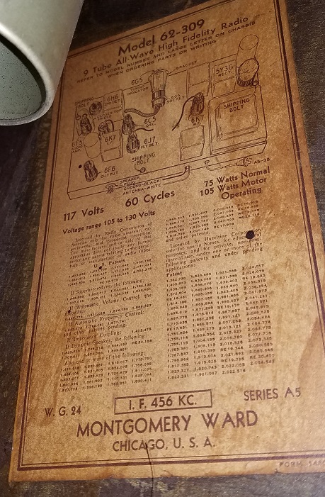
So as it stands what is the tube line up??
When my pals were reading comic books
I was down in the basement in my dad's
workshop. Perusing his Sam's Photofoacts
Vol 1-50 admiring the old set and trying to
figure out what all those squiggly meant.
Circa 1966
Now I think I've got!
Terry
Posts: 1,531
Threads: 242
Joined: Sep 2012
City: West Bend, Wisconsin
Here's what's in there now, along with the 6SC7
Greg V.
West Bend, WI
Member WARCI.org
Posts: 7,303
Threads: 269
Joined: Dec 2009
City: Roslyn Pa
I vote for removing the 6SC7 circuit. It's really poor placement putting it right next to the power transformer. The magnetic field generated by the transformer is bound to add some level of 60cy hum into the low level audio. Thought I saw a 6L6 plugged into the chassis? If so get rid of it too.
When my pals were reading comic books
I was down in the basement in my dad's
workshop. Perusing his Sam's Photofoacts
Vol 1-50 admiring the old set and trying to
figure out what all those squiggly meant.
Circa 1966
Now I think I've got!
Terry
Posts: 3,160
Threads: 59
Joined: Apr 2011
City: Lexington, KY
That's pretty interesting with all of the old modifications. One radio I needed to return to stock in the past I printed off the schematic and used colored pencils to trace the wiring and components as I brought them back to normal. In your case you might want to enlarge the schematic and just print off sections so it's easier to trace and follow.
I've only had one movie dial set and it did not have electric tuning, but all of my other sets with electric tuning were able to be tuned manually, so I'd check for something binding...... hopefully there isn't warped pot metal causing it.
John KK4ZLF
Lexington, KY
"illegitimis non carborundum"
Posts: 599
Threads: 24
Joined: Jan 2014
City: Edmonton AB CA
That 6SC7 tube was most likely added as a phono preamp. I have seen that tube used many times in this application and it makes sense with the addition of the switch and RCA jack, most likely a low level input in conjunction with a high level input or maybe the switch just isolates the radio from the phono. As Terry pointed out not the best mounting location and they are usually mounted on isolated tube sockets as well. If you don't need or want a phono input, remove it all.
Gregb
(This post was last modified: 04-24-2017, 10:21 AM by gregb.)
Posts: 203
Threads: 20
Joined: Feb 2017
City: Orland Park
State, Province, Country: Illiinois
Wow, that's one heck of a hackup...
Those radios are beauties, though
http://www.radiomuseum.org/images/radio/...560181.jpg
Greg
"We are here to laugh at the odds and live our lives so well that Death will tremble to take us."
Posts: 1,531
Threads: 242
Joined: Sep 2012
City: West Bend, Wisconsin
Managed to get the pushbutton assembly off of the chassis to see what's binding and keeping the tuning knob from working. The tuning capacitor is free and turns by hand as does the movie dial. One of the maze of gears, or even the motor itself is the culprit. Will investigate more tomorrow night.
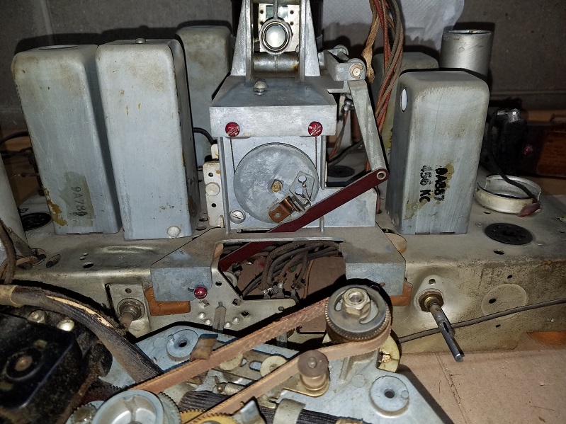
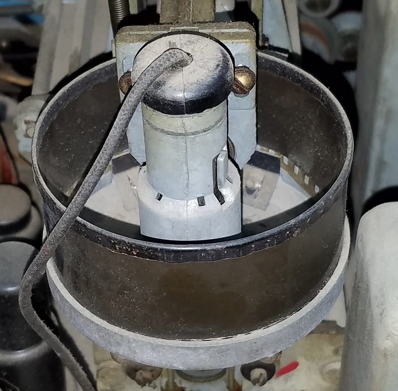
Does anyone know how to change the mazda bulb for the movie dial? How does it come out? Does that black tip come out with the bulb attached?
Greg V.
West Bend, WI
Member WARCI.org
Posts: 1,531
Threads: 242
Joined: Sep 2012
City: West Bend, Wisconsin
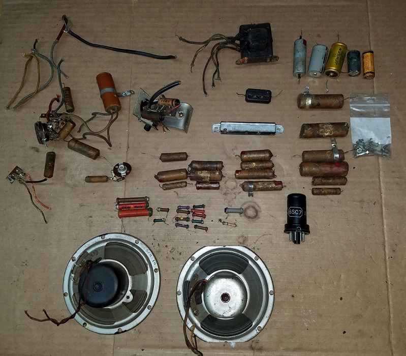
Just an update....by tracing out the entire schematic wire by wire and taking out what didn't belong and replacing what did with new caps and resistors, remarkably it came to life on the first try! Here's a pic of everything that was either removed altogether or what was replaced. The final assembly should take place over the weekend.
Greg V.
West Bend, WI
Member WARCI.org
Posts: 1,531
Threads: 242
Joined: Sep 2012
City: West Bend, Wisconsin
Greg V.
West Bend, WI
Member WARCI.org
Posts: 5,182
Threads: 276
Joined: Nov 2012
City: Wilsonville
State, Province, Country: OR
Posts: 203
Threads: 20
Joined: Feb 2017
City: Orland Park
State, Province, Country: Illiinois
I can't believe all the junk you pulled out of that thing. That's a beautiful radio, nice job!
Greg
"We are here to laugh at the odds and live our lives so well that Death will tremble to take us."
Posts: 16,533
Threads: 573
Joined: Oct 2011
City: Jackson
State, Province, Country: NJ
Greg, nice job and nice radio.
People who do not drink, do not smoke, do not eat red meat will one day feel really stupid lying there and dying from nothing.
Posts: 1,475
Threads: 69
Joined: Nov 2012
City: Kansas city, MO.
Beautiful radio! Great job on your restoration. 
Users browsing this thread: 1 Guest(s)
|
|
Recent Posts
|
|
Philco newbie with P-1891-WA console questions
|
| Well, I've been stumped at trying to get the first of 11 electrolytic capacitors. I got a schematic and have a list of t...Jeffcon — 07:54 PM |
|
Model 80 Antenna Issue?
|
| Thanks Gary and Rod.
I also found an article in the Philco Repair Bench under Service Hints and Tips, about installi...Hamilton — 12:32 PM |
|
Model 80 Antenna Issue?
|
| Hello Hamilton, here is a little information found in our Philco Radio Library at the bottom of the Home page. Hope it ...GarySP — 11:28 AM |
|
Model 80 Antenna Issue?
|
| I did as you suggested and touching the middle of the volume control did nothing so the coil has to be rewound. Any idea...Hamilton — 10:19 AM |
|
1949 Motorola 5A9M
|
| This would be the second portable in the "other radios" forum where I have a similar one in my collection. I h...Arran — 12:41 AM |
|
Looking for any info: 1977 Ford-Philco Console Hi-Fi Turntable and Radio
|
| Hi PittsburgTost.
The record changer looks like a Garrard or BSR (Likely Garrard). The spindles just pull out and pu...MrFixr55 — 11:57 PM |
|
Looking for any info: 1977 Ford-Philco Console Hi-Fi Turntable and Radio
|
| Hello PittsburghToast ,
Welcome aboard and it looks like gary may have something for you !
now if I dig through my se...radiorich — 11:35 PM |
|
Model 80 Antenna Issue?
|
| You are kind of on the right path. You can touch the grid cap of the Detector/Oscillator 36 tube. I'm expecting a respon...RodB — 08:48 PM |
|
Looking for any info: 1977 Ford-Philco Console Hi-Fi Turntable and Radio
|
| Welcome to the Phorum, PittsburghToast! I found an old thread that my interest you regarding the quality and worth of P...GarySP — 08:48 PM |
|
Looking for any info: 1977 Ford-Philco Console Hi-Fi Turntable and Radio
|
| Welcome to the Phorum!
:wave:
We do not have anything on that unit in our digital library. There is a Sam's Photof...klondike98 — 08:47 PM |
|
Who's Online
|
There are currently 1042 online users. [Complete List]
» 1 Member(s) | 1041 Guest(s)
|
|
|

|
 
|


![[-] [-]](https://philcoradio.com/phorum/images/bootbb/collapse.png)


