Posts: 1,199
Threads: 49
Joined: Oct 2017
City: Allendale, MI
A week ago I posted pics in November phinds of a 112X I picked up for $20. here are some picks of the chassis restoration. PLEASE let me know if I'm doing something that greatly reduces value. I'm relatively new at this so I want to learn.
Chassis before:
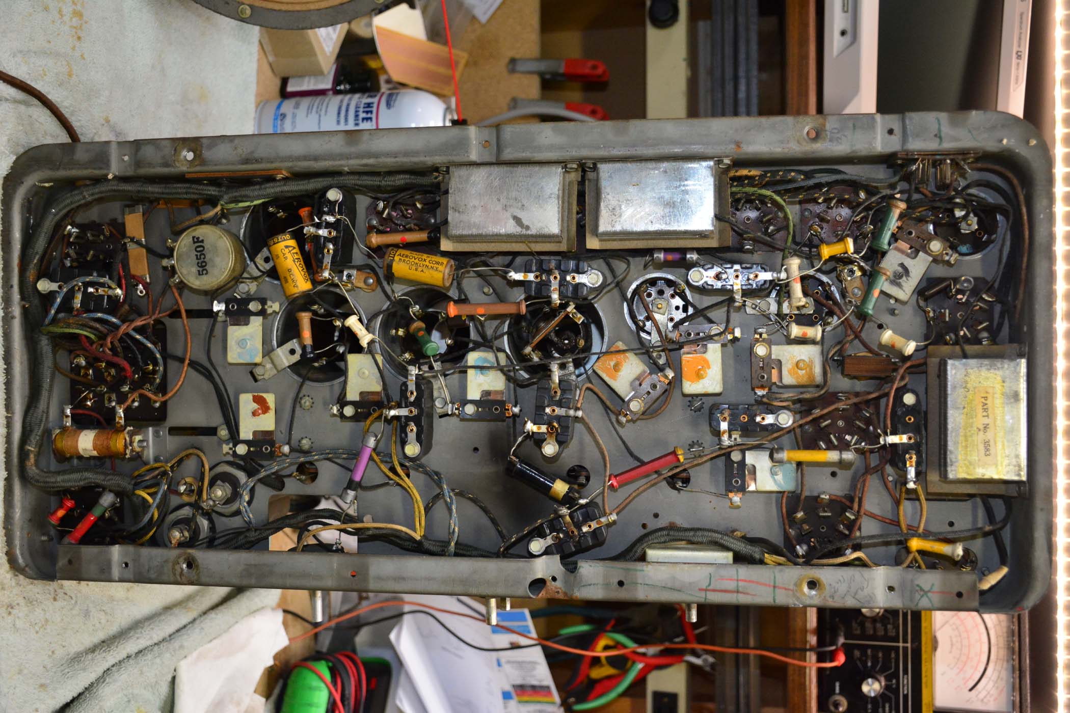
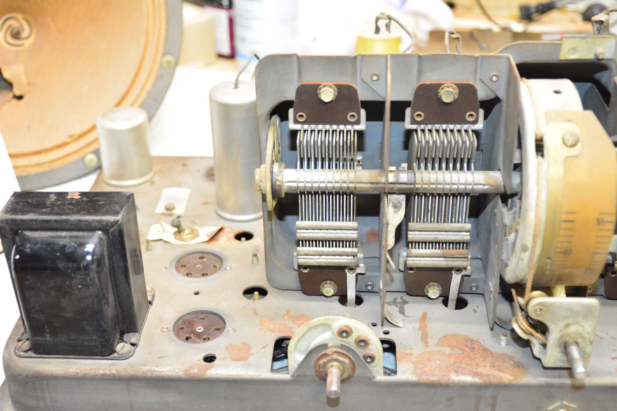
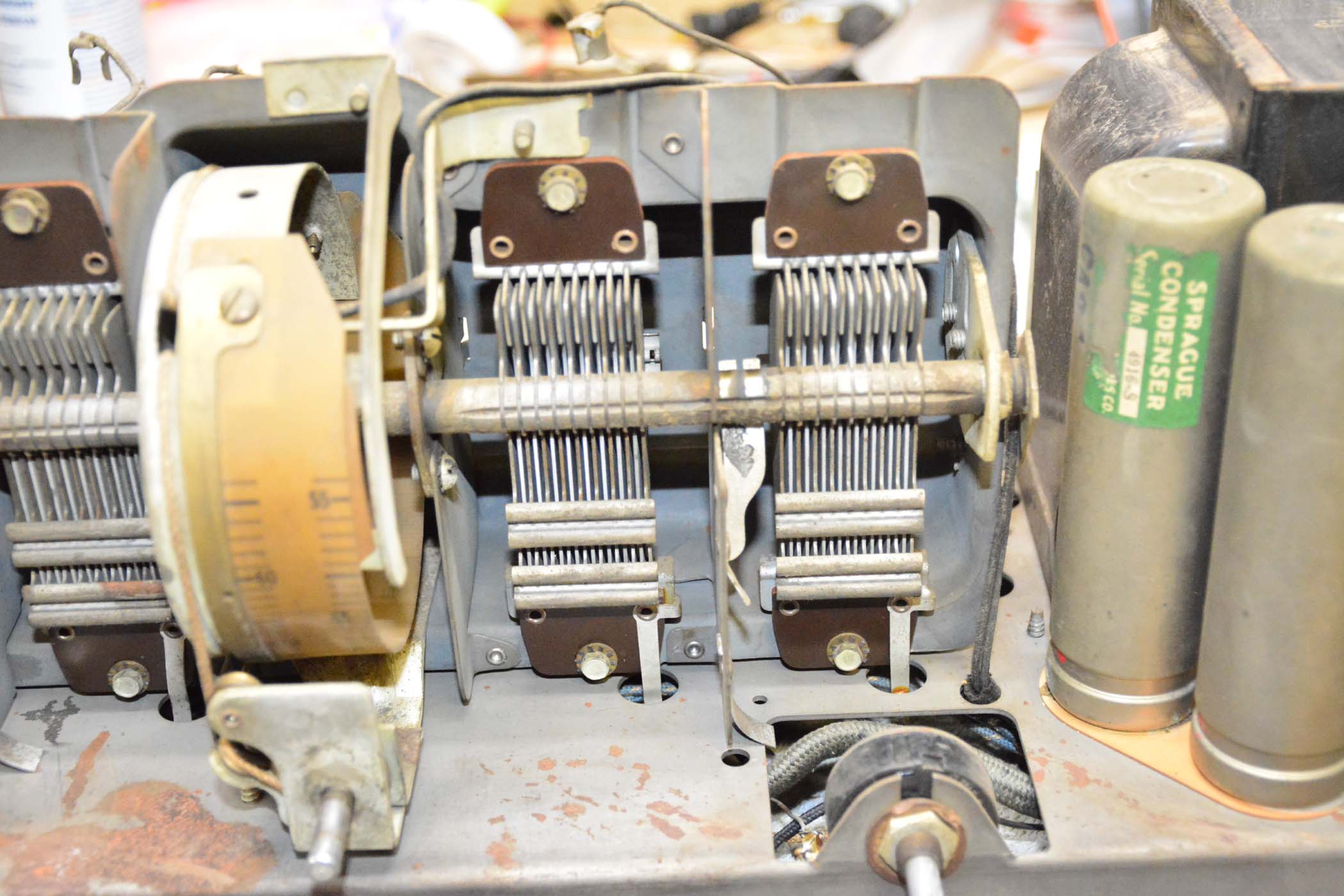
(continued)
Posts: 1,199
Threads: 49
Joined: Oct 2017
City: Allendale, MI
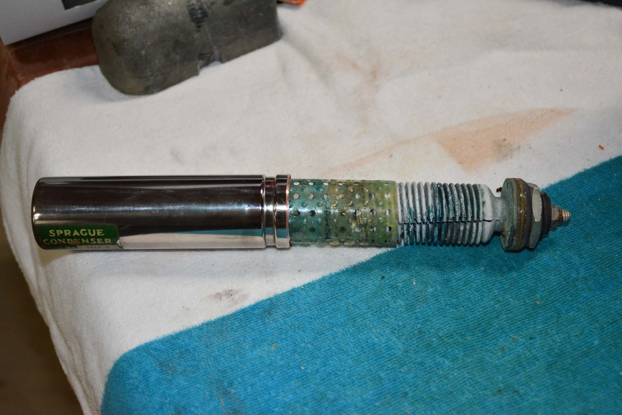
Sprague nickel plated caps:
belt sander used to sand off crimp:
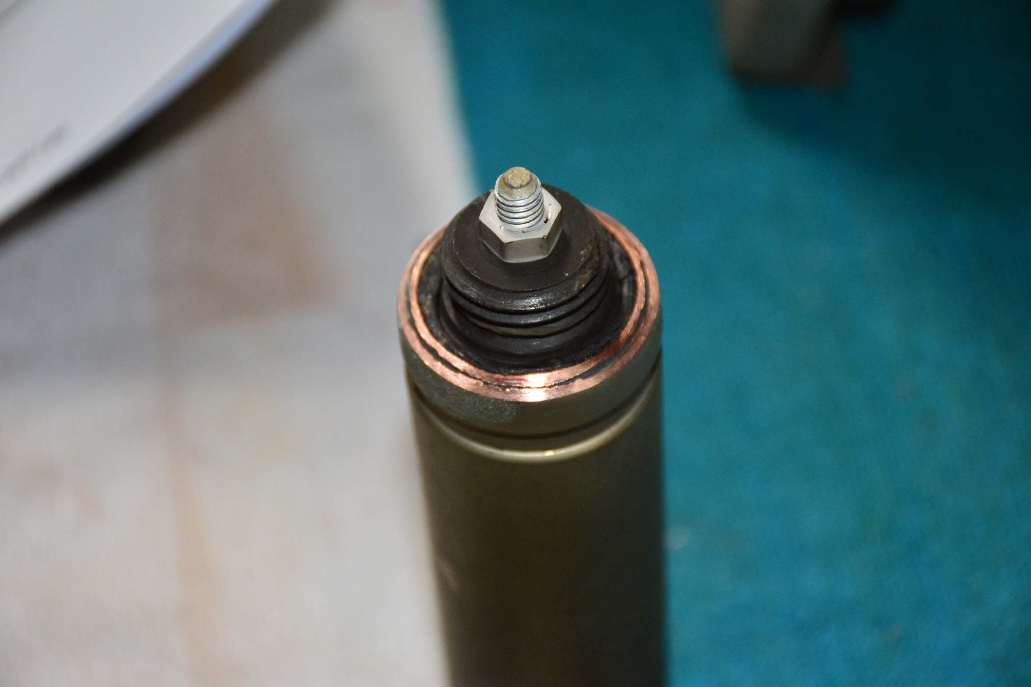
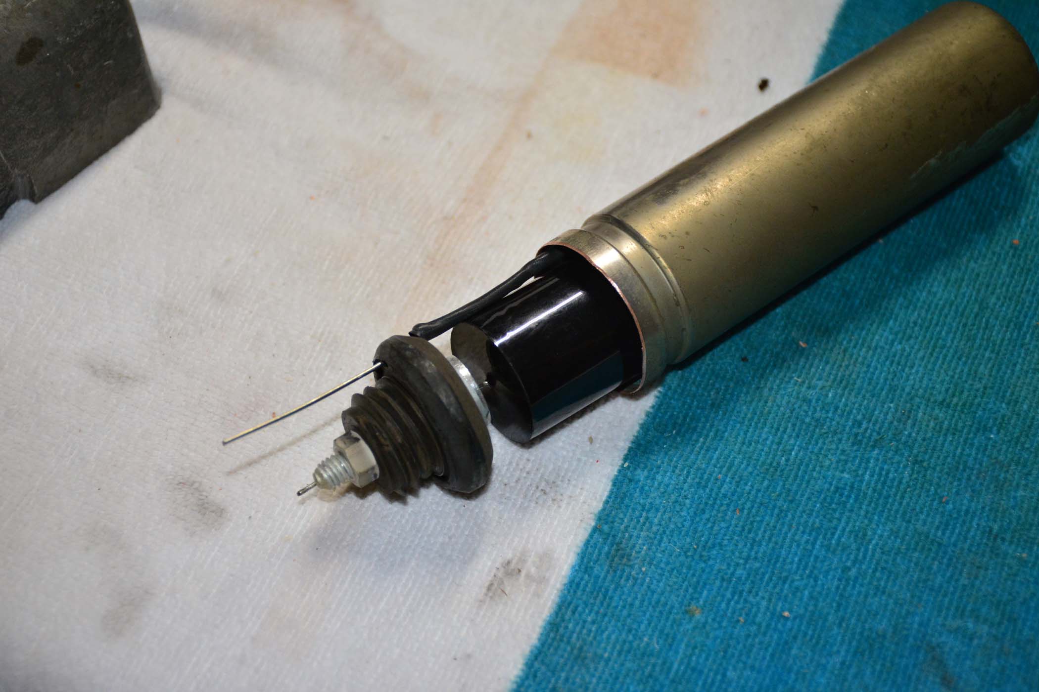
Innards removed:
New cap:
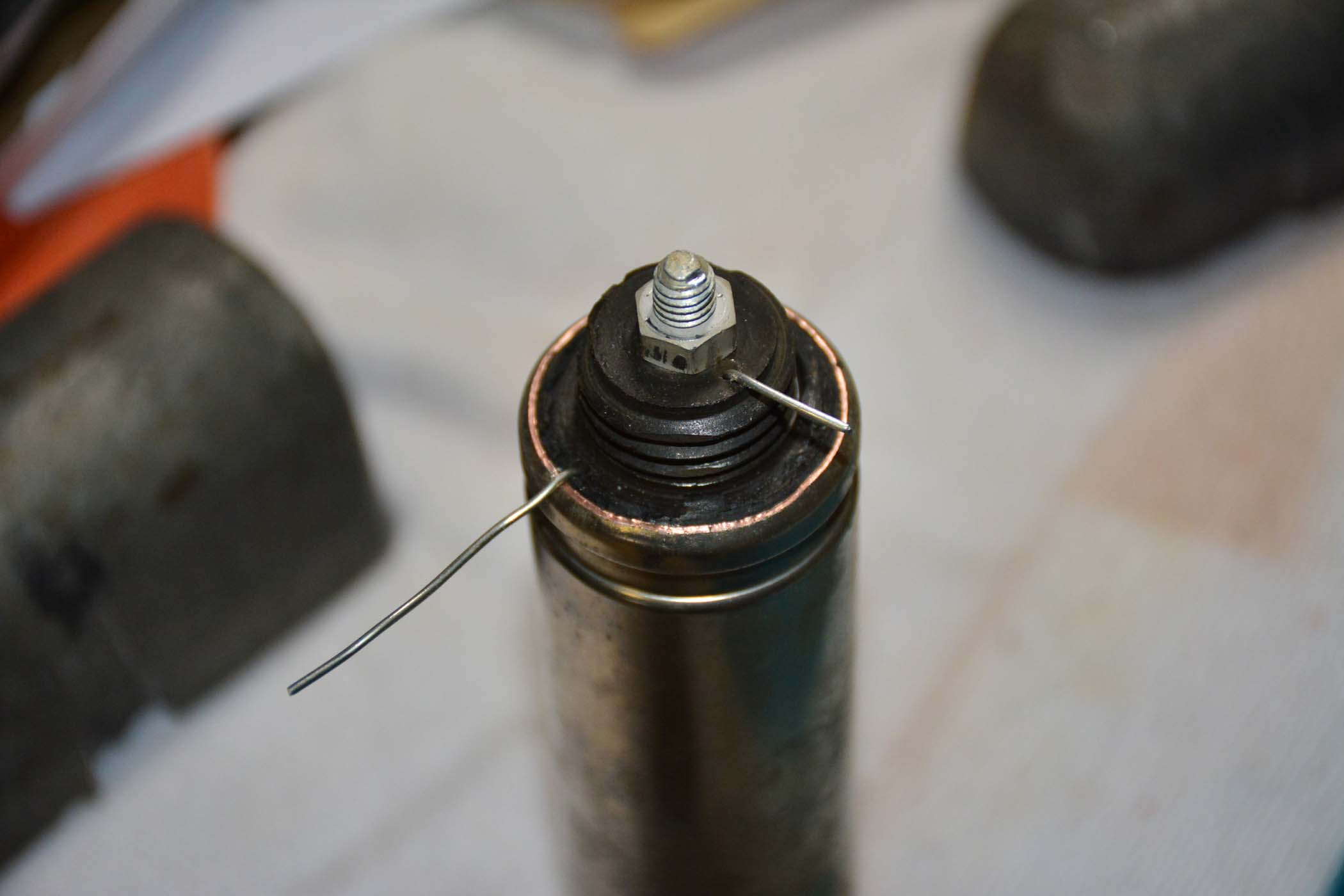
Edge re-crimped:
Posts: 1,199
Threads: 49
Joined: Oct 2017
City: Allendale, MI
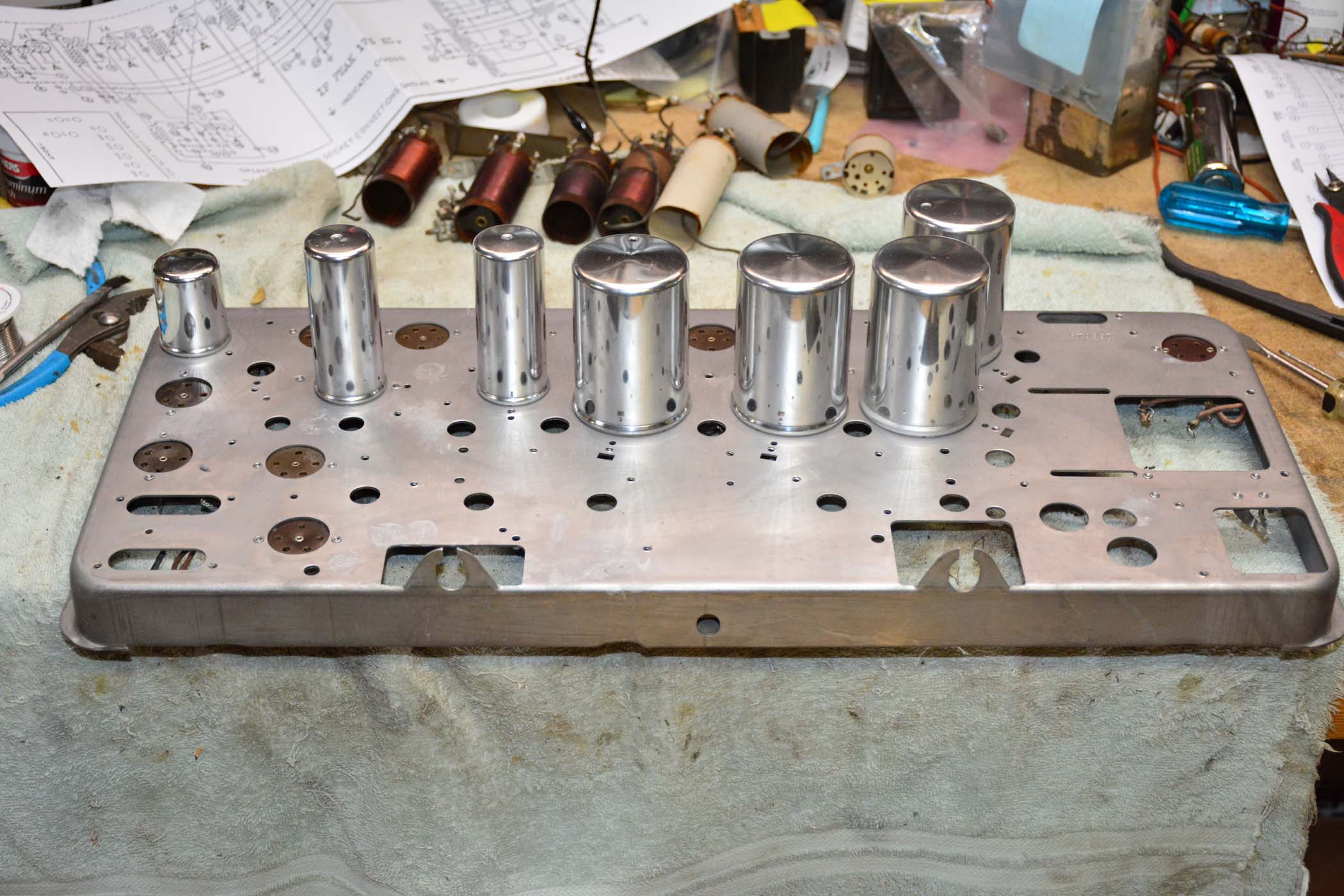
Chassis in process:
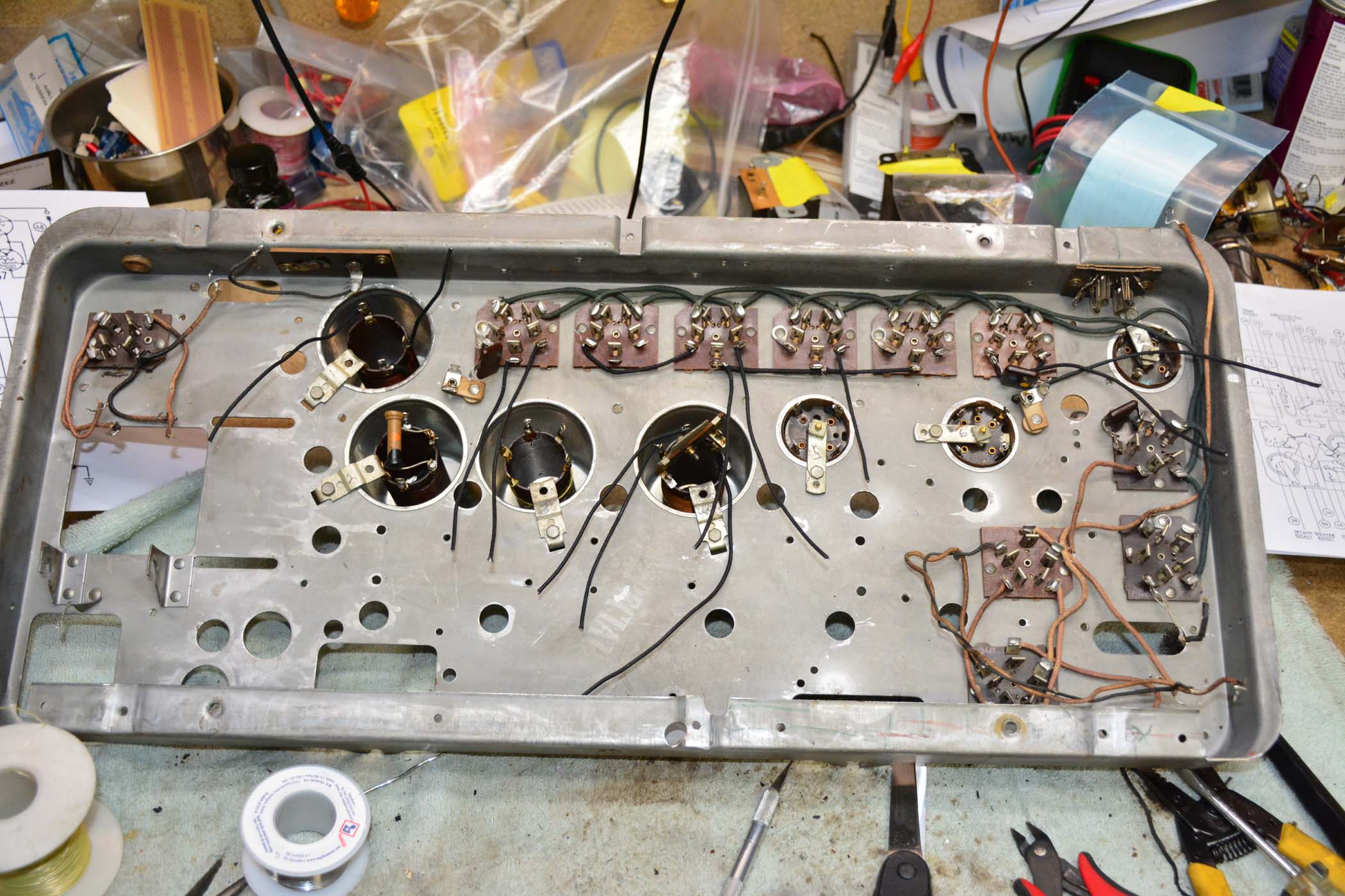
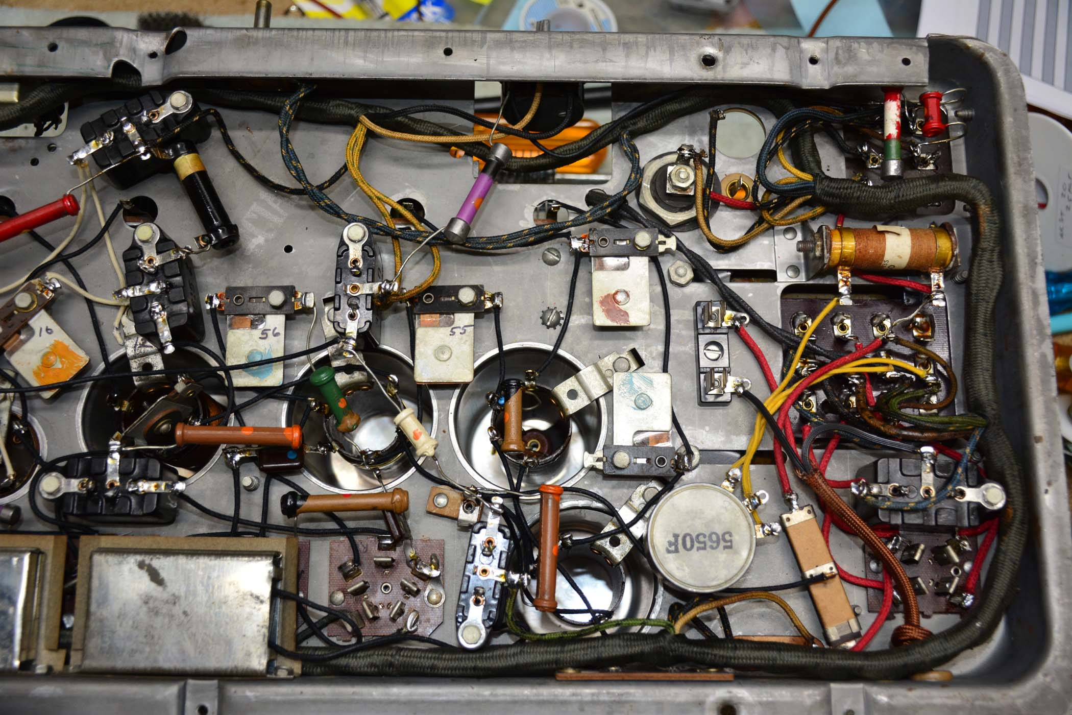
After solving a couple of problems, the 112X plays again!
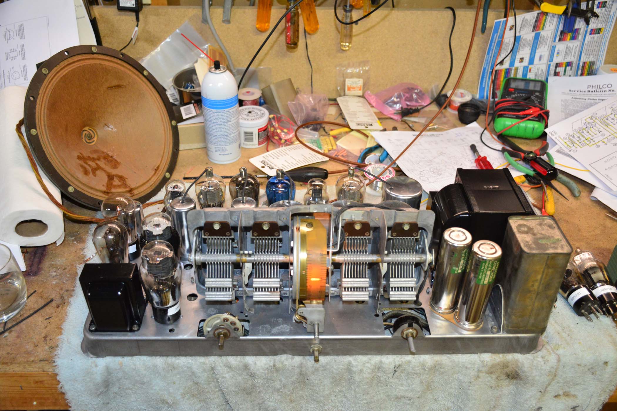
Now to start the cabinet which will need much more work than the radio chassis!
One problem I have with this tuner, the same problem I had with the 96 I did with the same tuning capacitor, is that the plates of the moving portion of the capacitors are heavy and cause the thing to want to rotate when on the high end of the dial. After cleaning and lubricating the assembly, there is not enough friction in the system to overcome the weight of the tuning plates hanging out. On the 96 I added a lead counter weight inside the circular dial. Perhaps I shouldn't use lubricant on the bearings!
Posts: 4,905
Threads: 54
Joined: Sep 2008
City: Sandwick, BC, CA
You might be able to fix that by adjusting a cup on the end of the tuning condenser shaft, I don't know about the tuning condensers used in Philco pan chassis sets but most tuning caps have an adjustment on the opposite end for adjusting lash. One end of the tuning condenser has a point on it, and this point rides in a cup that is threaded into the end plate, as well as a locking nut to hold the adjustment in place. I had to back one of those off on one set because the condenser had the opposite problem, it was really stiff and no about of solvent or oil would free it up, like it had one 99% of the others I had worked on.
Regards
Arran
P.S If you want to preserve the value of the set, at least historically, and want to include a fusei, nstall a fused plug, like the 38-690 used, rather then an automotive fuse holder. Ron got one from a farm supply, used for electric fences. The auto ones are not approved for use on 120 volt appliances, and look terrible under the chassis.
(This post was last modified: 12-03-2018, 02:47 AM by Arran.)
Posts: 1,199
Threads: 49
Joined: Oct 2017
City: Allendale, MI
Thanks Arran. As you can see, I did put a fuse holder under the chassis but it is not the typical low voltage automotive type. It is a Bakelite, high voltage holder as has been used in some of the organs I have serviced for years. I'll look into the fused plug, though. that may be a neater, simpler solution to protecting things in case of a TR failure or something. For the sake of safety and to avoid the 60 volt tickle, I've often considered a 3 wire plug/cord connection. I did that on one of my shop radios and I like not getting the tickle when touching the chassis. Certainly not original, but...
As far as the adjustment on the end of the capacitor rod is concerned, these don't have that. it seems they relied on friction in the system, particularly the dial drive pulleys, to hold a setting. I know the bearings and the grounding "brushes" were lubed with something. it looks like it might have been some sort of graphite grease. For now, I put in some felt that rubs against the dial drum. that seems to hold the settings.
The radio is working great even with very weak tubes!
(This post was last modified: 12-03-2018, 03:14 AM by rfeenstra.)
Posts: 16,533
Threads: 573
Joined: Oct 2011
City: Jackson
State, Province, Country: NJ
112 is probably one of the easiest chassis to restore. All of these large chassis are not too bad, I have done at least two, one of the 111 which is 112 but with the old capacitors block; the 112 is the best as it no longer has this huge block which all other radios before it did, and this one is a bear to empty (I still haven't done my 85's box, the caps are sticking out without the cover). This block is the Philco-20 type and is much easier, though still creates a mess with all that tar chips 
People who do not drink, do not smoke, do not eat red meat will one day feel really stupid lying there and dying from nothing.
Posts: 189
Threads: 22
Joined: Aug 2018
City: Kewanee
State, Province, Country: Illinois
Great job it looks like really nice work!
1929 Victor R-32, 1933 60L, Phil 40-158, Phil 42-400X, Phil 47-1230 Radio/Phono,, 1950 Phil TV t-1104, Air King 4000, Philco 41-105, Philco 37-675, RCA Victor 9K2, PT-50, Phil 54C, PT-44 Cabinet, Phil 118X Cabinet
Gregg 
Users browsing this thread: 1 Guest(s)
|
|
Recent Posts
|
|
Philco 91 code 221
|
| Dirty tube pins and socket, cold solder joint, stray tiny strand of wire, clean the entire area around the oscillator tu...RodB — 08:43 PM |
|
Philco 91 code 221
|
| I have been restoring one of these sets and switched it on yesterday. It didn't exactly spring into life, but after a co...Philconut — 08:26 PM |
|
Philco 50-925 antenna connections
|
| That's super. Glad to hear you figured it out. Paul.Paul Philco322 — 11:11 AM |
|
Philco 50-925 antenna connections
|
| Hello Keith,
great news !!
Sincerely Richardradiorich — 02:14 AM |
|
Philco 50-925 antenna connections
|
| Finally, got the antenna fixed (repaired some broken wires) and have the radio playing. I've got four different schemat...keith49vj3 — 09:38 PM |
|
1949 Motorola 5A9M
|
| Bob, Nice radio. I’ve not seen one before. Keep us updated!Joe Rossi — 07:56 PM |
|
Phioco 90 Power Transformer Wire Colors
|
| Thanks for adding that information.klondike98 — 06:09 PM |
|
Phioco 90 Power Transformer Wire Colors
|
| Although I have used this site as a resource for a number of years this is my first post. I am restoring a Model 90 si...vincer — 05:02 PM |
|
My collection presentation
|
| There is a complete instruction how to solve your problem. One piece of advice - be careful with the low-voltage capacit...Vlad95 — 09:32 AM |
|
My collection presentation
|
| Vlad;
I thought your brown RCA portable looked familiar, I have one that is very similar, the RCA-Victor model BX-55....Arran — 02:31 AM |
|
Who's Online
|
| There are currently no members online. |

|
 
|


![[-] [-]](https://philcoradio.com/phorum/images/bootbb/collapse.png)


