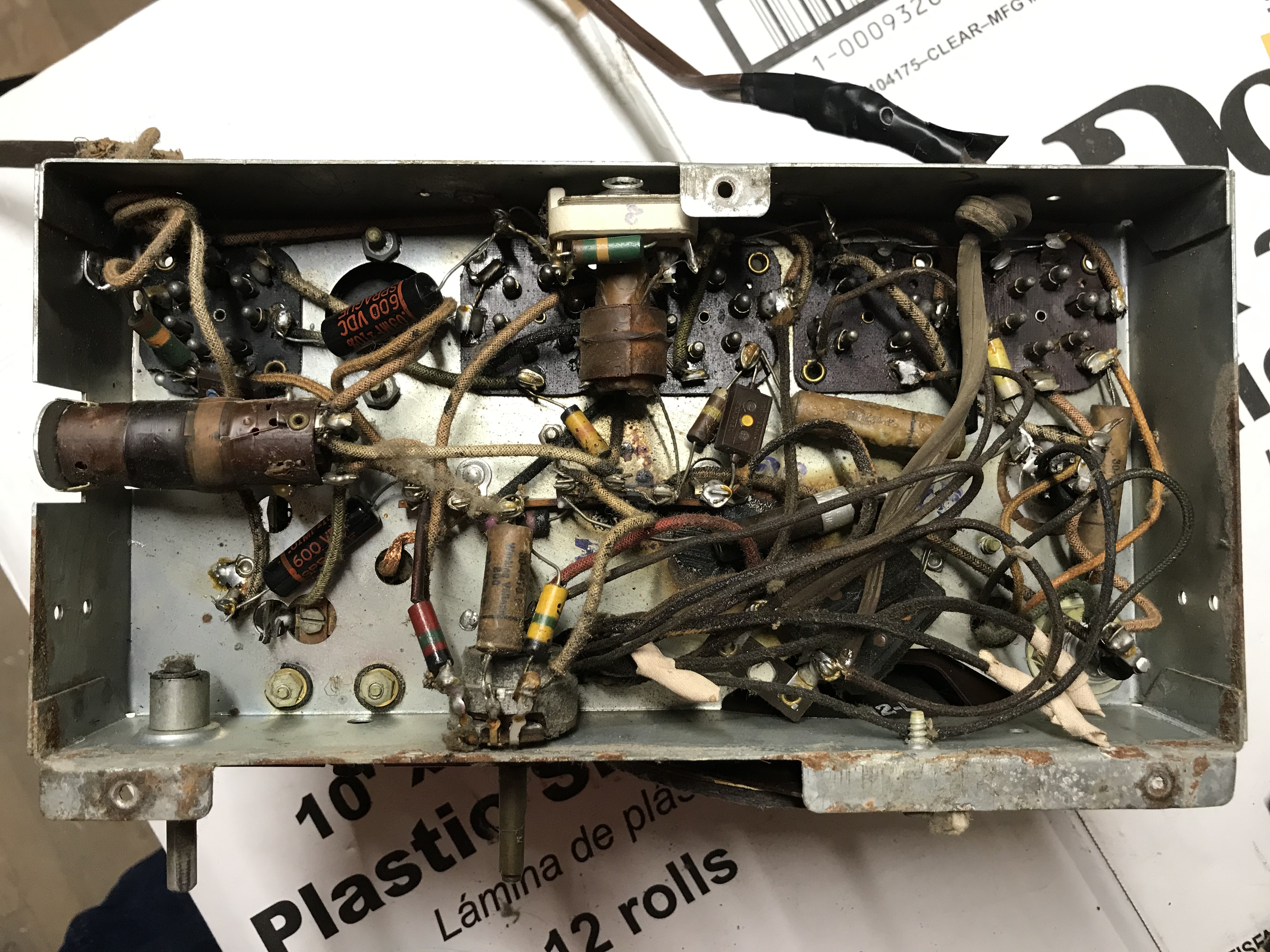
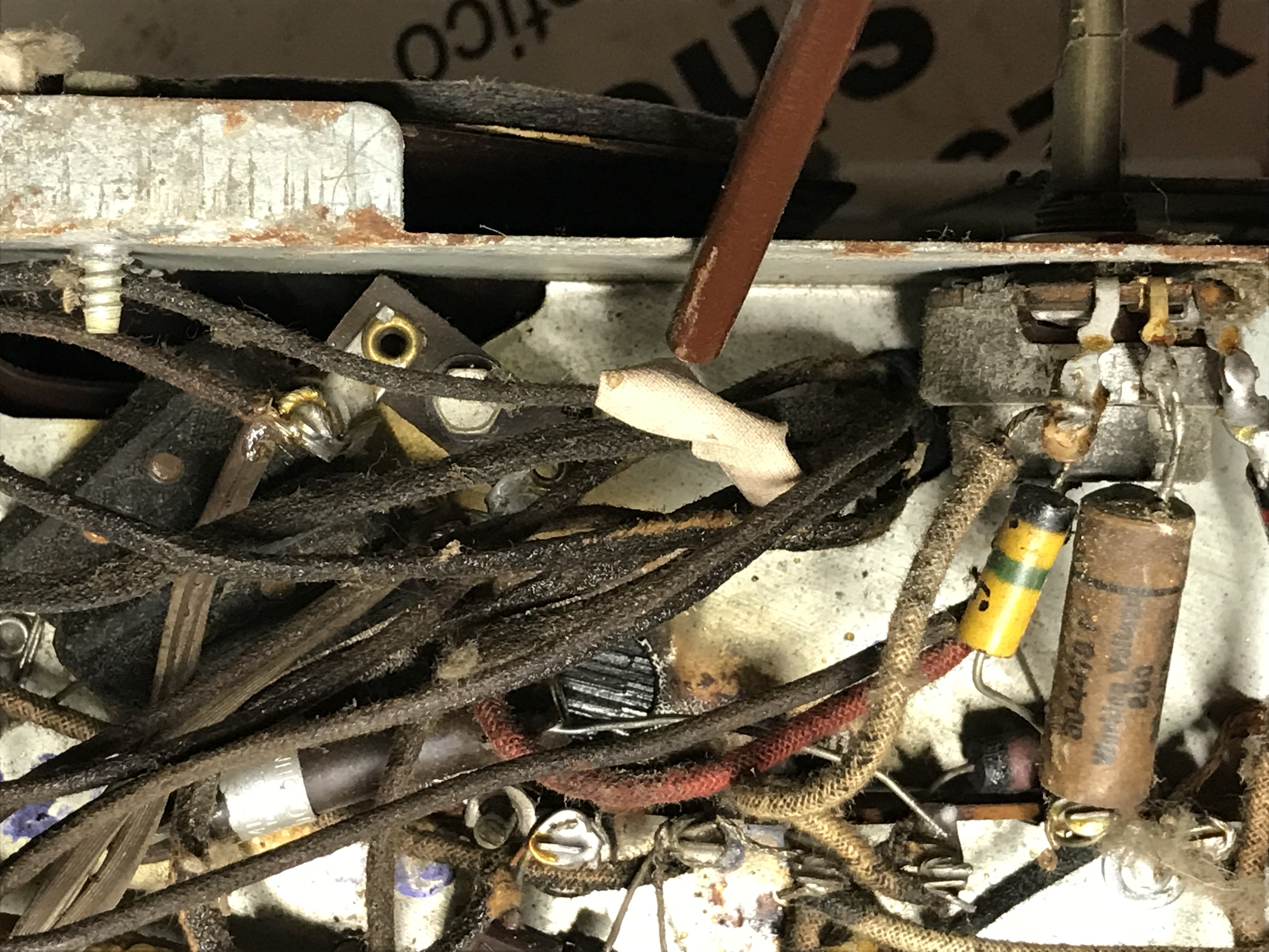
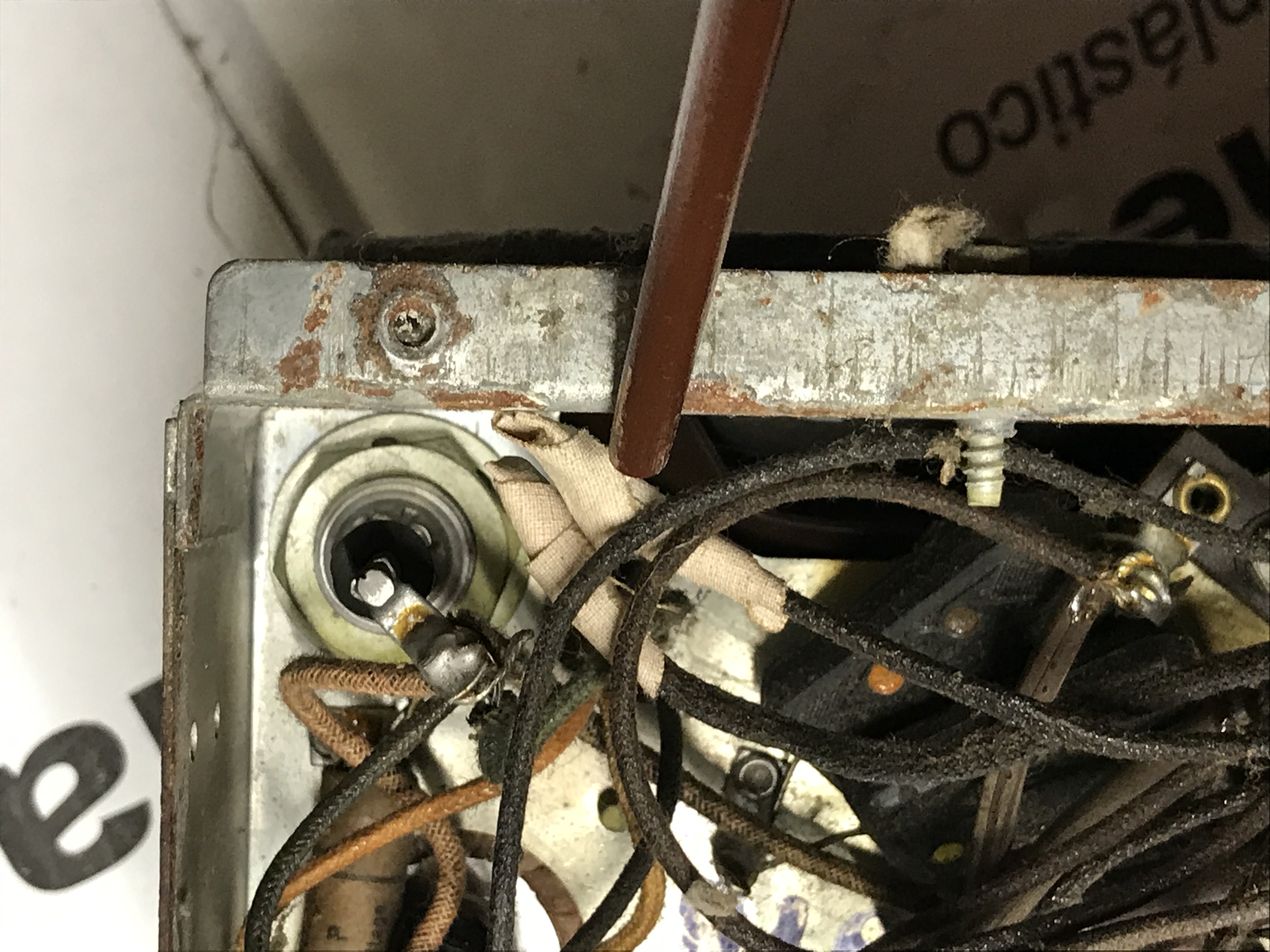
I am attaching photos of the 38-12 chassis I just pulled out. I am confused (but have a theory) as to where the bakelite fuse is. I suspect that since the area where it should be is scorched that there was a problem in the past in which it was removed. There are also these "extra" leads coming out from the transformer that have been capped (taped) off and, again, I think these went to the bakelite. The radio plays so I'm scratching my head as to what was done, if it is safe, and can it be left the way it is after recapping? I will be replacing all paper caps and electrolytics. Thanks for your help.


|
38-12 Chassis confusion
10-17-2019, 01:21 PM
Fuse is not original to the radio, it was installed by a restorer. The radio was restored likely in 50-s or 60-s - the black tubular capacitors are from that era.
Scorched place might be a poorly insulated wire splice touching the chassis. If you want to restore to the original state - you have to trace and compare to the schematic. It is not difficult as the AC power part is simple. Since you have the fuse, might as well keep it and wire it appropriately. People who do not drink, do not smoke, do not eat red meat will one day feel really stupid lying there and dying from nothing.
10-17-2019, 01:26 PM
The bakelite block (Item# 30 in the schematic) was not a fuse. It contained two 0.01uF capacitors that served as line filters. One side of each cap was connected to the input power line and the other side of each cap went to ground.
10-17-2019, 01:47 PM
Oh....I think I mistook the electrolytic cap for the fuse someone put into and thought that was the part in question.
Yes, what Bob said. Again, there is no fuses in the original radio (nor there were in most or all Philco radios....there was one in the sentertap of the speaker transformer in 38-690). People who do not drink, do not smoke, do not eat red meat will one day feel really stupid lying there and dying from nothing.
10-17-2019, 02:02 PM
OK, you confirmed my thoughts. Some work was done earlier. Still a bit confused as to whether I need to go beyond recapping. At the risk of repeating myself, any ideas on the leads from the transformer that are taped off?
10-17-2019, 02:59 PM
Its pretty hard to trace those transformer leads by just looking at the picture, at least for me. A couple of things to do:
1) trace each wire to see where it goes and mark it off on the schematic, maybe even put a small label on it. Then if you have marked off all the leads on the schematic but still have the two unknown leads in the chassis, I would expect you have a replacement transformer that had some extra windings not used in this set. or 2) you will find where they were supposed to go and then can hopefully sort it out from there. Tracing the wires takes a bit of patience but isn't too hard.
10-17-2019, 04:31 PM
Owing to the length of those transformer leads, the transformer was obviously replaced at some point and the repairman did not cut off excess wire leads (poor practice).
Perhaps the taped-off leads are for an unused 5V winding? Just a guess. -- Ron Ramirez Ferdinand IN
10-17-2019, 08:16 PM
Yeeeees, thank you for the input. It makes sense now with the missing bakelite housing, scorched chassis, extra wires, partial recap. Looks like radio had a mishap and was repaired, albeit poorly.
« Next Oldest | Next Newest »
Users browsing this thread: 1 Guest(s) |
|

|


![[-] [-]](https://philcoradio.com/phorum/images/bootbb/collapse.png)

