Posts: 451
Threads: 85
Joined: Nov 2011
City: Cumming, GA
Good Morning!
I have a Zenith 6D015 with a missing loop antenna. Here is the info.
http://www.nostalgiaair.org/pagesbymodel...025061.pdf
I want to make a loop to improve reception which is not that bad but still I would like to improve it.
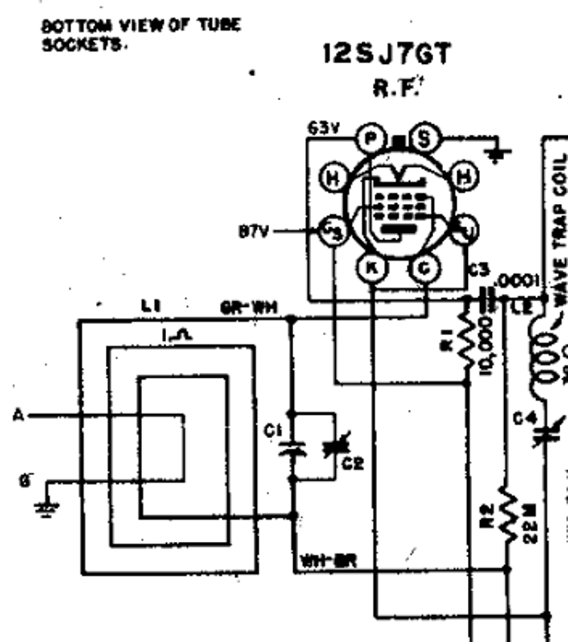
My questions are on the schematic for the loop shows a wire marked A (antenna) & G (ground)? Does this wire in any way connect to the chassis? It shows just looping the antenna loop. Am I looking at it correctly?
Thanks
Eric
Posts: 3,160
Threads: 59
Joined: Apr 2011
City: Lexington, KY
I might be wrong, but I think the A and G connections are where you hook an external antenna.
John KK4ZLF
Lexington, KY
"illegitimis non carborundum"
Posts: 451
Threads: 85
Joined: Nov 2011
City: Cumming, GA
John
That is what I figure but it stumps me that it appears to just pass through as it doesn't look like a connection on the loop or it wouldn't be the first time the schematic is not accurate and it is connected. From pictures on Radiomuseum it appears to have connections.
https://www.radiomuseum.org/r/zenith_6d0...6c05z.html
https://www.radiomuseum.org/r/zenith_6d0...h6c05.html
https://www.radiomuseum.org/r/zenith_6d0...h6c05.html
Don't know if these links will work but here we go.
Posts: 3,160
Threads: 59
Joined: Apr 2011
City: Lexington, KY
I think it must hook to the chassis somewhere, but without having one to actually examine it's hard to tell from the RM pictures.
John KK4ZLF
Lexington, KY
"illegitimis non carborundum"
Posts: 714
Threads: 9
Joined: Apr 2018
City: S. Dartmouth
State, Province, Country: MA
The antenna is one or more turns around the existing loop and exits with a wire (terminal) that gets connected to an earth ground. The antenna/ground is not connected to the chassis.
Pliny the younger
“nihil novum nihil varium nihil quod non semel spectasse sufficiat”
Posts: 451
Threads: 85
Joined: Nov 2011
City: Cumming, GA
Thanks all for the feedback, between the pictures, print and my looking for evidence of leads that might have been cut I think I have figured it out. It is a simple loop with one lead to the top of the tuning condenser and the other to that frame as I found a stub of a lead sticking out from under the other soldered lead. So I tied a loop I had at those points and it works very well.
Eric
Posts: 714
Threads: 9
Joined: Apr 2018
City: S. Dartmouth
State, Province, Country: MA
Eric,
I gather that the original Zenith "loop" is not in place, another loop may not have the correct inductance, but that can be fixed.
Look at the RF stage schema, the loop that is tuned is connected to the stator of the tuning condenser, (not the oscillator section) AND the loop returns to the AVC line, that wire may be soldered to the bottom of the tuning condenser frame and schema says "WH-BRN" a wire with a tracer, that is AVC... The tuning condenser frame is insulated from the chassis.
If the cold end of the loop is connected to chassis there will be no control over the RF amp, AVC will work poorly.
But, if your happy...

Oh goody, that printed nice and big

If after connecting as shown in schema and the radio works poorly, then the "new" loop will have to have turns added or removed. There is a trick to determine what to do but only if you need to tune that loop... chas
Pliny the younger
“nihil novum nihil varium nihil quod non semel spectasse sufficiat”
(This post was last modified: 12-11-2020, 01:00 PM by
Chas.
Edit Reason: error
)


![[-] [-]](https://philcoradio.com/phorum/images/bootbb/collapse.png)


