Philco 39-116 restoration final issues - mystery wire and bluetooth audio clipping
Posts: 4
Threads: 1
Joined: Jan 2026
City: Saskatoon
State, Province, Country: Canada
I picked up a 39-116 (technically 39-3116 Canadian version) a few months ago and have completed recapping and installing a bluetooth transmitter.
This is my first old radio and my knowledge of the inner workings are minimal at best so I've been flying blind for the most part and trying to navigate the schematics available.
I have two issues.
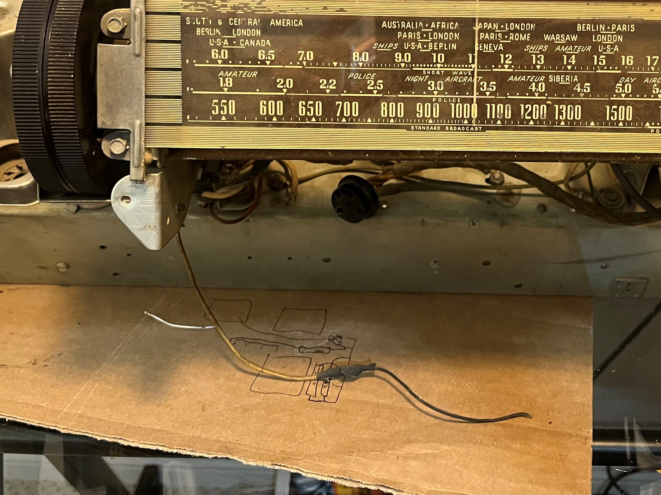
First, as I went through everything I realized that the radio has been fairly significantly worked over at some point with entire circuits added and added/changed wiring. I've been able to trace most things down but there is one beige wire that goes out the front of the cabinet that has been poorly spliced at some point and is no longer connected to anything.
Inside the cabinet it is connected to a terminal of a wave switch near the oscillator transformer. I've circled it in red in the attached picture. The wire runs out the front of the cabinet and terminates near the wiring for the preset bulbs. I haven't been able to locate any obvious spots where it may have broken off. Notably, the wire is rubber coated and the majority of the other wiring is cloth under the cabinet. Rubber coated wiring is used for the light bulb wiring elsewhere.
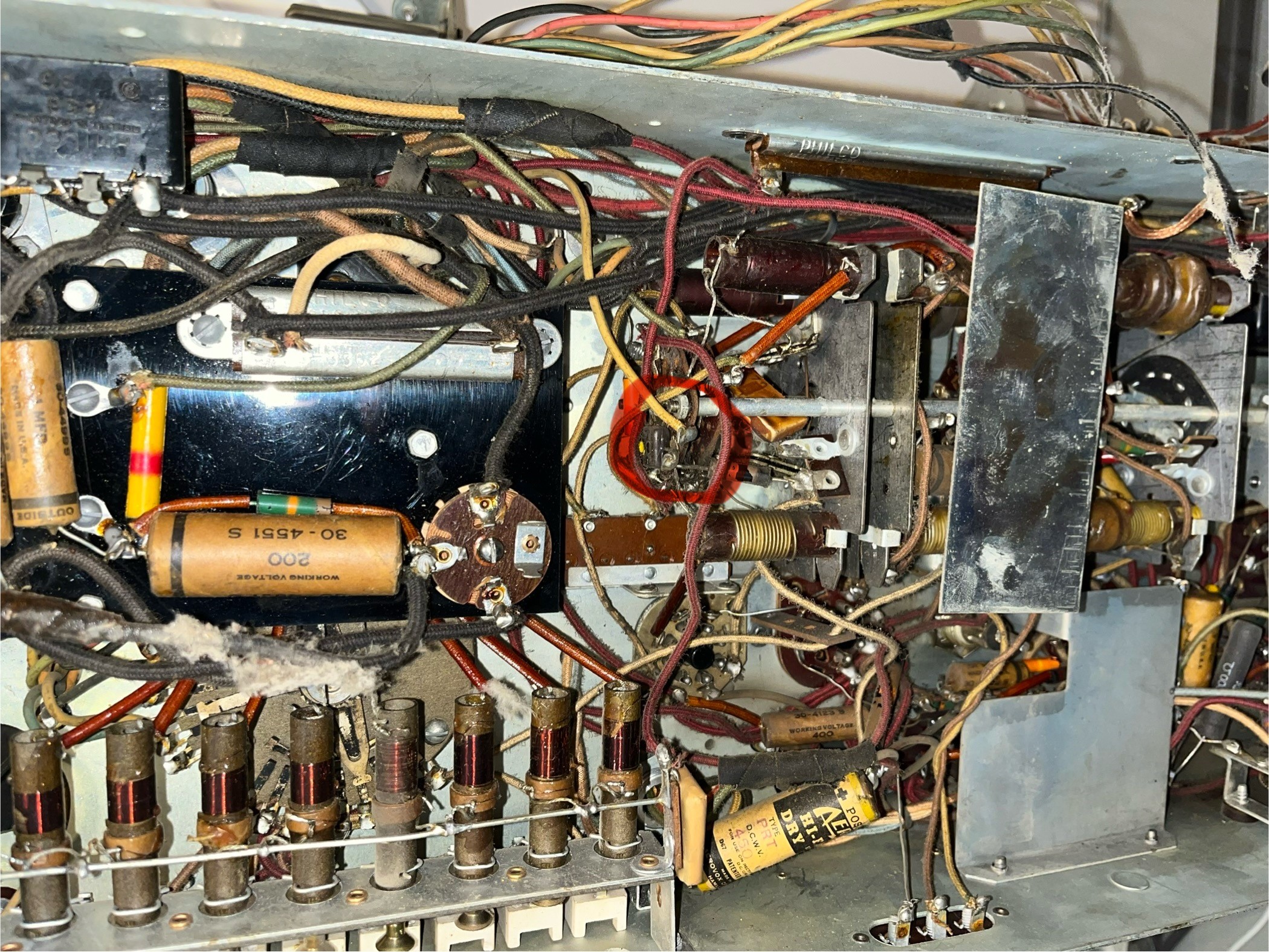
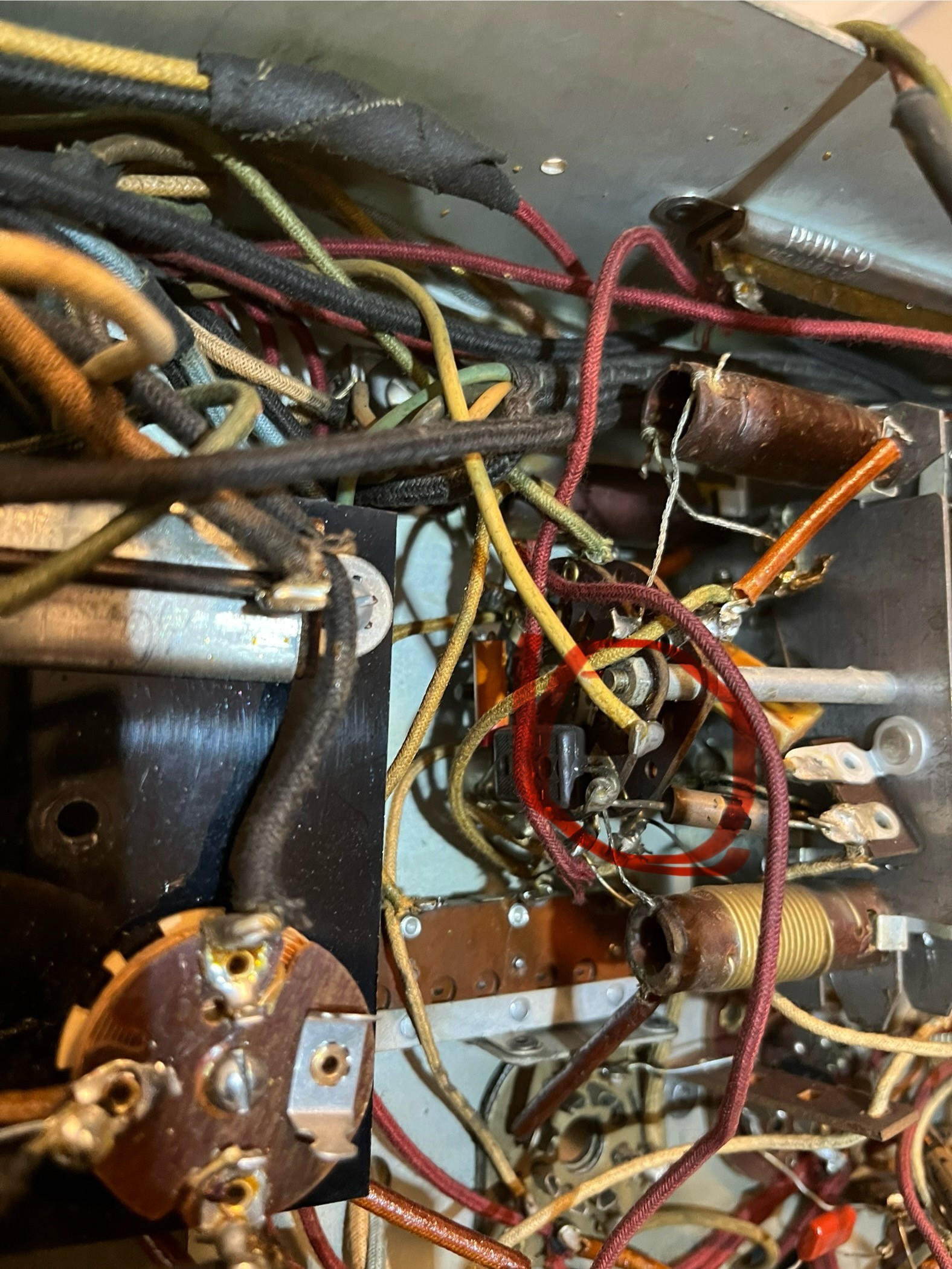
The second issue is with regard to the volume potentiometer. When I initially powered the unit on, I was not getting any sound except for in one position on the pot. I suspect this is where it sat for many years. I've taken the potentiometer apart and cleaned it multiple times with de-oxit, I now have good sound in that one position (about half volume) but scratchy/distorted sound if I try to go any louder. I suspect I'll have to try replacing it.
The related issue I'm having is with the bluetooth input. It has its own power supply and the output is wired directly to the volume potentiometer (stereo output to 10k resistors that are tied together and then wired to the pot). If I try to increase the volume above about half way on my phone or the bluetooth module, as soon as there is too much audio input the sound will cut out/clip. I haven't seen this issue mentioned elsewhere with bluetooth adapters. I suspect the input is overpowering the position of the pot somehow, or maybe is just related to the already iffy potentiometer, but would appreciate input from more knowledgable people than myself.
Thanks,
Jeff
(This post was last modified: 03-18-2026, 03:17 PM by Jefftrex.)
Posts: 5,584
Threads: 291
Joined: Nov 2012
City: Wilsonville
State, Province, Country: OR
Welcome to the Phorum

So folks can follow along here's a link to the US version schematic 39-116 from our digital library:
https://philcoradio.com/library/download...20Book.pdf
You did not pick an easy one for your first radio restoration so taking your time will be important. Take lots of photos as you go along; as much as possible change out one thing at a time.
There are two types of deoxit, one for metal contact cleaning and one for variable resistor/potentiometer cleaning. The metal cleaner is in a red can and the pot cleaner is in a green can. Using the red can on pots can clean off the coating used for the variable resistor in some cases. That may not be what's happing in your case though. Mark Oppat does do restoration of pots and you can contact him at his web site. Here's the controls page: https://www.oldradioparts.net/controls.htm
Posts: 4
Threads: 1
Joined: Jan 2026
City: Saskatoon
State, Province, Country: Canada
Thanks Bob, I will likely reach out to Mark about a replacement pot.
I’ve actually finished recapping already and am just trying to troubleshoot these final items. It was definitely a challenge.
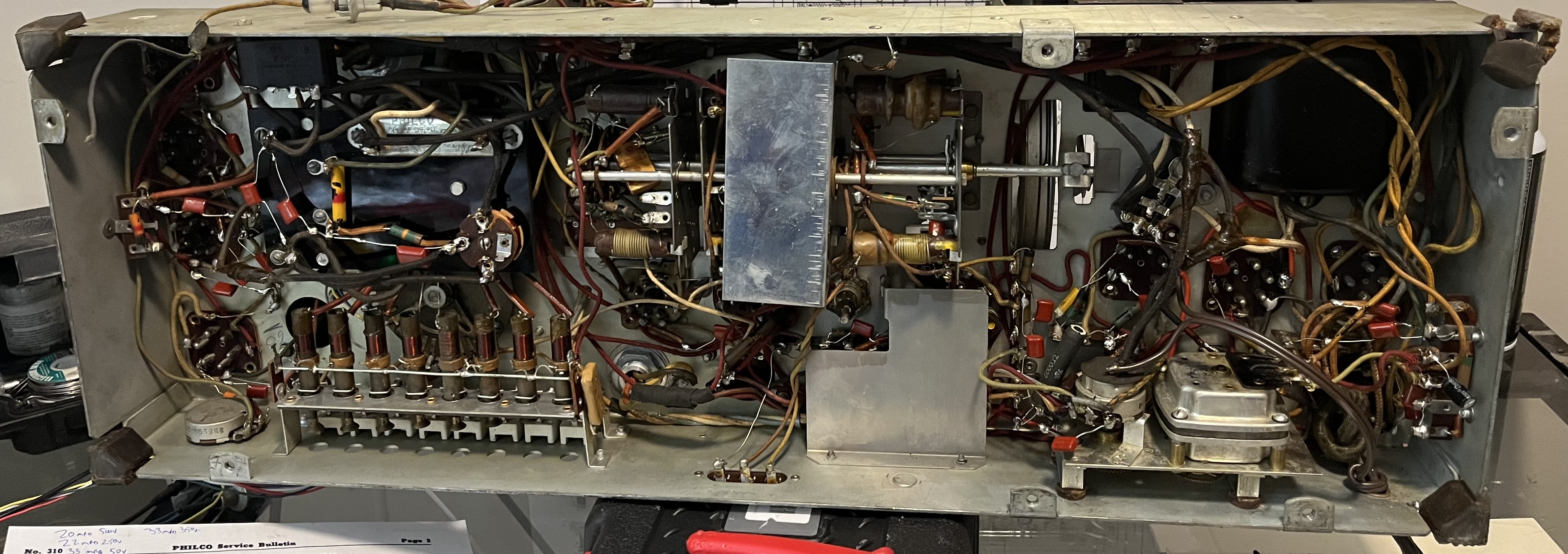
Posts: 5,584
Threads: 291
Joined: Nov 2012
City: Wilsonville
State, Province, Country: OR
My only thought on the loose wire is that it might be an antenna wire. I think the wafer switch assembly its connected to is the band selection switch and the addition of the taped on black wire at the end of the white wire suggests a longer antenna wire may have been attached. You might be able to trace back through the wafer switch connections to see how it connects into the circuit. The "D" wafer is associated with the antenna transformers if I'm reading things correctly. I always have difficulty tracing through wafer switches!
Posts: 75
Threads: 7
Joined: Oct 2017
City: bloomfield, ct
Hi Jefftrex,
Good luck on the restoration of your 39-116. I finished one a couple of years ago. I consulted my notes and I believe that that yellow wire you questioned is the feed for the station lights when the set is set for remote operation. it looks to be connected to position 1 on the "A" wafer on the band switch. When the band switch is in the "remote" position, "A1" connects to "A3" which supplies 6V power through resistor # 82 (10 ohms) for the station bulb lights. On the schematic, it is located on the lower right, just above the MOTOR part # 80.
Hope this helps.
Fran
Posts: 75
Threads: 7
Joined: Oct 2017
City: bloomfield, ct
Ah, it all comes back to me now. That yellow wire is soldered to the base of the first (left most) station light, and when the light socket is pushed into position in the metal holder, it supplies the 6-volt feed to all the other station lights through the bases. They are grounded through the colored wires when the correct station position on the rotary switch is reached (through ground #81).
Fran
Posts: 4
Threads: 1
Joined: Jan 2026
City: Saskatoon
State, Province, Country: Canada
Thanks Fran, that makes perfect sense. I reskinned the wiring for the station lights but never thought about needing a power and ground for each while I was doing so.
Jeff
Posts: 5,584
Threads: 291
Joined: Nov 2012
City: Wilsonville
State, Province, Country: OR
I also thank you Fran...I see I counted the wafers backwards. Should have realized the oscillator transformer is attached to the A wafer, not the D wafer 
Posts: 4
Threads: 1
Joined: Jan 2026
City: Saskatoon
State, Province, Country: Canada
By way of update, I think I’ve determined the source of the clipping audio issue.
Every time I’d tested the radio I had it plugged into my dim bulb tester and I think this was limiting the power available both for the radio and the Bluetooth module. I plugged it straight into power this evening and am getting significantly more volume out of the radio now without running into the clipping issue.
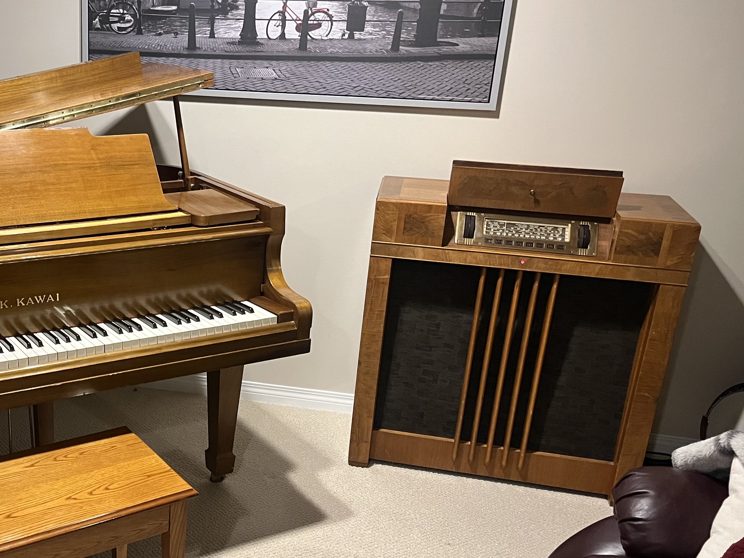
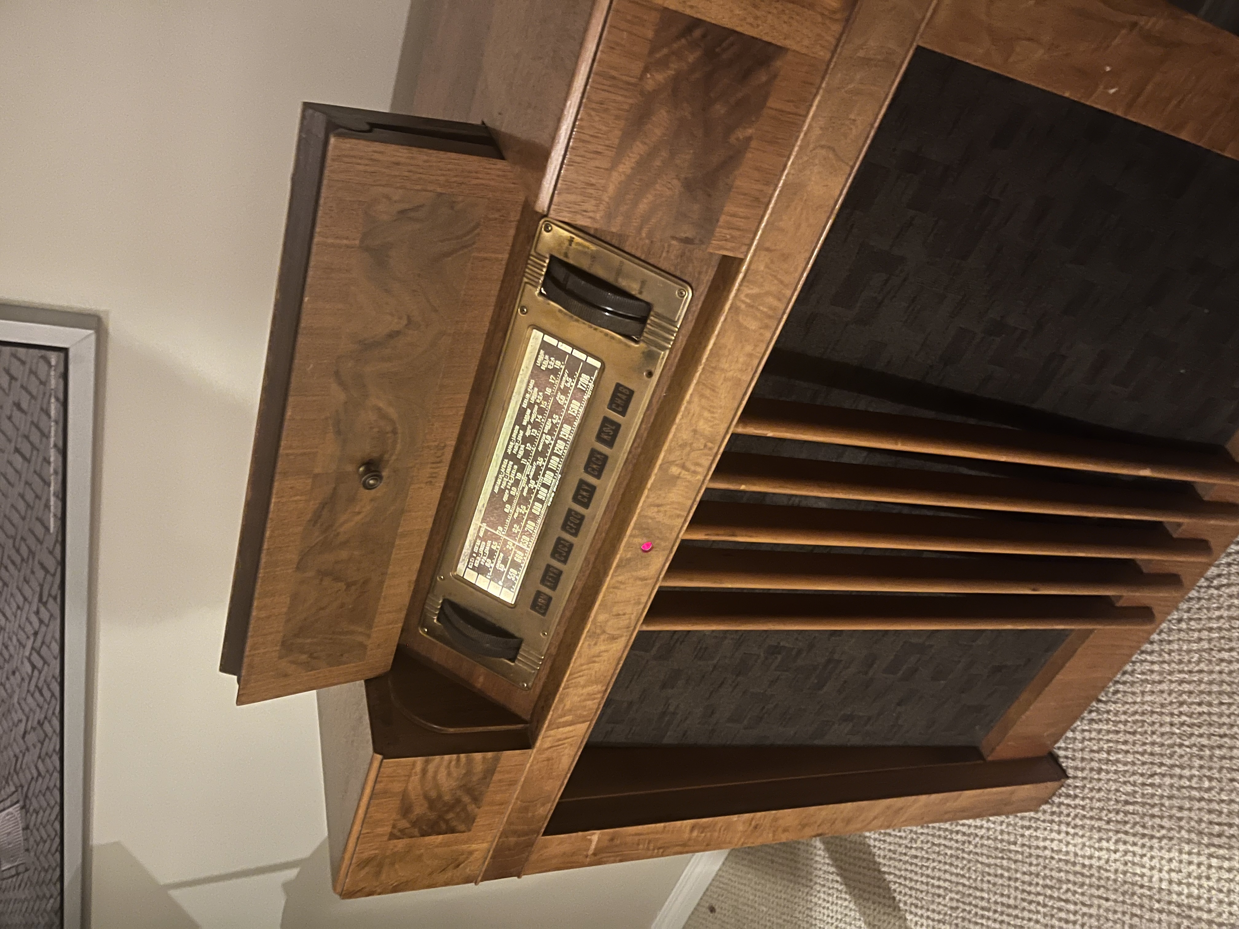
It makes a nice match for our piano. If anyone has a mystery control they’d be willing to part with, I may be interested.
Jeff
Posts: 18,427
Threads: 622
Joined: Oct 2011
City: Jackson
State, Province, Country: NJ
Mystery Controls are regulars on eBay.
People who do not drink, do not smoke, do not eat red meat will one day feel really stupid lying there and dying from nothing.
Posts: 711
Threads: 46
Joined: Sep 2009
City: Lapeer, MI
State, Province, Country: USA
Nice radio! I love the grille cloth. Nice piano... Joe
Courage will follow when Faith takes the lead.
(This post was last modified: 03-27-2026, 07:33 AM by Joe Rossi.)
Posts: 18,427
Threads: 622
Joined: Oct 2011
City: Jackson
State, Province, Country: NJ
Kawai is one of a few things available in the US that are still made in Japan. From what I heard, while the quality of it and Yamaha are the same Japanese quality, the tone is different and some prefer it as a bit more mellow.
I had a piano as a kid, and it was a good one, older construction Soviet-made in 60s, black.
When I went to study to music school, they had the ones with slanted front and shorter height, the sound was inferior.
We sold it before we decided to come to the US, as I moved out and there was no one to play it anymore. I hope it still has a good home.
People who do not drink, do not smoke, do not eat red meat will one day feel really stupid lying there and dying from nothing.
Users browsing this thread: 1 Guest(s)
|
|
Recent Posts
|
|
Philco P45-6365 Universal Transformer Instruction Manual
|
| Can anyone guide me to where this may be found?GRG — 03:00 PM |
|
54C Complete Teardown/Rebuild
|
| I don't think that I have encountered a 12Z3 before, curious how it uses one of those but includes a #43, which is a 25 ...Arran — 02:17 PM |
|
HiFi (Chifi) tube amp build - but my own design.
|
| It's the other forum. I'm also in DIY, but mostly read there. Honestly, I kinda jumped into this without much thought to...TV MAN — 10:43 AM |
|
Philco 71 Code 125
|
| Hello,
I am in need of a schematic for this radio. Mine has the three separate circular tube shields and a shadow me...dconant — 08:06 AM |
|
Stromberg Carlson 1500 Squeal
|
| And life just keeps getting more complicated.dconant — 07:57 AM |
|
54C Complete Teardown/Rebuild
|
| Hello Roy,
here is this one
sincerely Richardradiorich — 12:45 AM |
|
54C Complete Teardown/Rebuild
|
| Richard,
Had grabbed it already but thank you just the same. I find myself wanting to find some way to block out the...glyphmon — 12:03 AM |
|
54C Complete Teardown/Rebuild
|
| Hello roy,
here is a link to the schematic .
Sincerely Richardradiorich — 11:54 PM |
|
54C Complete Teardown/Rebuild
|
| Richard,
The Silvertone 2014 also is a transformerless set, so I am incorporating a 1:1 600 ohm audio isolation transfo...glyphmon — 11:37 PM |
|
Preliminary work on wife's Silvertone 2014
|
| Did an alignment today which was interesting. IF alignment went great, almost all was already spot-on. Adjusting on th...glyphmon — 11:35 PM |
|
Who's Online
|
| There are currently no members online. |

|
 
|








