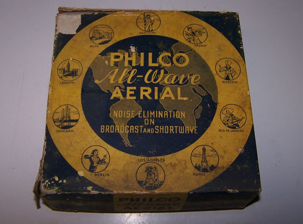
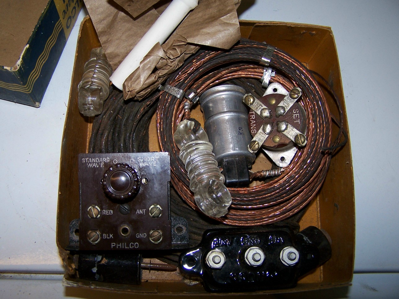
A 1937 Accessory Philco Antenna
Posts: 309
Threads: 55
Joined: Oct 2011
City: Claremont, NH
OK, so I'm surfing the bay kinda late and all of a sudden this Philco accessory antenna pops up. Well I have never seen one before and it even is in it's original box. I don't know if it is all there, but I know I want it! So I hit the BIN button and here it is. I figure I won't hook it up, but display it with my Philco's.
[Image: http://i1185.photobucket.com/albums/z345...406c95.jpg]
[Image: http://i1185.photobucket.com/albums/z345...7c3f49.jpg]
[Image: http://i1185.photobucket.com/albums/z345...6ab587.jpg]
[Image: http://i1185.photobucket.com/albums/z345...afadce.jpg]
[Image: http://i1185.photobucket.com/albums/z345...d65095.jpg]
Gene
(This post was last modified: 03-08-2013, 10:17 PM by Gene Pederson.)
Posts: 1,411
Threads: 71
Joined: Oct 2007
City: Linn Creek, MO
Now, that was a great find   
Steve
M R Radios C M Tubes
Posts: 73
Threads: 11
Joined: Feb 2012
Outstanding find though I'm a bit preplexed, where does the AC power cord come in to play? Surely not an RF amplifier or is it an earlier version of the 60's phony TV antenna advertised in cheap magazines proporting
the use of the house AC system as a fantastic TV antenna. If so it
would be much more sucessful on AM and SW frequencies than on
the NTSC VHF and UHF bands.
Posts: 344
Threads: 38
Joined: Jun 2011
City: Tustin
State, Province, Country: California
Very nice Gene! It is interesting how many were purchased and never used. I have a 1938 that is very similar to your 1937 antenna, and I have this one from 1939 or 1940. I'd like to use one and
see how well they perform 


(This post was last modified: 02-11-2013, 01:39 AM by thirtiesradio.)
Posts: 244
Threads: 11
Joined: Oct 2011
City: Black Mountain, NC
The AC type plug is where the antenna plugs into the side of the radio cabinet in most cases. I bet some folks got a shock when the did put AC voltage into that connector by accident....
Great find. Maybe you can post a pdf of the instruction manual so we can replicate.
Thanks,
Mike
Cossor 3468
GE 417A
Philco 118H
Radiola 17/100
Scott 800B6
Silvertone 6130
Stromberg 535M
Truetone D1952
Posts: 309
Threads: 55
Joined: Oct 2011
City: Claremont, NH
MIke,
I will try to get the info scanned a post it.
Gene
Posts: 481
Threads: 18
Joined: Jan 2013
City: Mesa, AZ
My uncle (born 1910) told me a long time ago they would run one wire from the antenna lead directly into the neutral side of the electrical outlet for reception.  This was around 1975, he had an old Airline SW receiver. I didn't really believe him, but he demonstrated (after i sought shelter on the other side of the room). Yes, it actually made a huge difference in the reception. I believe he said that all the wiring in the house had to be correct for it to work. I would never try this myself, nor recommend it, but it did work. 
Posts: 1,411
Threads: 71
Joined: Oct 2007
City: Linn Creek, MO
You're right, it's not a good plan. 
Steve
M R Radios C M Tubes
Posts: 244
Threads: 11
Joined: Oct 2011
City: Black Mountain, NC
Gene,
Thanks much. Look forward to seeing it.
Mike
Cossor 3468
GE 417A
Philco 118H
Radiola 17/100
Scott 800B6
Silvertone 6130
Stromberg 535M
Truetone D1952
Posts: 309
Threads: 55
Joined: Oct 2011
City: Claremont, NH
Here are two pics of a second antenna I picked up. Note on this one as in the pic from thirtiesradio there are two coils of copper wire that may have been cut off of the first one I bought??
[Image: http://i1185.photobucket.com/albums/z345...a4847d.jpg]
[Image: http://i1185.photobucket.com/albums/z345...ccf9b7.jpg]
Gene
Posts: 309
Threads: 55
Joined: Oct 2011
City: Claremont, NH
Thirtiesradio,
I have seen that bakelite box in your set with the dial on it on the back of a radio that came up for sale on the bay. I didn't know what it was for but now it becomes very clear.
Gene
(This post was last modified: 03-09-2013, 12:40 AM by Gene Pederson.)
Posts: 337
Threads: 15
Joined: Nov 2005
City: Ortonville, MI
Yep. the bare twisted copper lines were cut from the first kit shown. What the AC plug was for is a mystery. Don't try to use it for anything!
The kit had this stuff: Two lengths of bare copper twisted wire, which were the two doublet legs. They connected to the "balun" transformer in the aluminum can. The lead-in to the set goes from the balun to the set. There is an insulator tube for the lead-in or the ground wire (The single conductor insulated wire). There is a ground clamp for a water pipe, and the porcelain lightning arrestor. there should be an instruction sheet in the kit.
My father bought a Philco 37-650 new for Christmas, 1936, and one of these kits was supplied with the set. Father never did install the antenna kit as recommended, and probably very few ever were. The lead-in nhad rubber insulation on the conductors, and that will be all dried out, long since.
Whatever that
Posts: 2,353
Threads: 92
Joined: May 2010
City: Clayton, NC
The early AC sets often had features that allowed the owner to use house AC service wiring as an antenna. Many pre-1930 Philcos did this.
Posts: 309
Threads: 55
Joined: Oct 2011
City: Claremont, NH
Thanks for the info on these Doug! I would love to be able to hook one up.
Maybe I can splice some copper wire onto the one that got cut and then see if I can assemble it to one of my Philco's.
Ya never know, I just might pick up Sir Winston Churchill broadcasting..............................in the "Twilight Zone". 
Using the house wiring as an antenna is a pretty uncomfortable idea  
Gene
(This post was last modified: 03-10-2013, 10:28 AM by Gene Pederson.)
Posts: 481
Threads: 18
Joined: Jan 2013
City: Mesa, AZ
Maybe that's why so many of those antenna are still left in good condition today - you had to plug them in, and people were leery of getting shocked or burning their house down. Like I said earlier in this post - that little trick actually DOES work, but who among us is brave enough to try it? 
Users browsing this thread: 1 Guest(s)
|
|
Recent Posts
|
|
Philco newbie with P-1891-WA console questions
|
| Well, I've been stumped at trying to get the first of 11 electrolytic capacitors. I got a schematic and have a list of t...Jeffcon — 07:54 PM |
|
Model 80 Antenna Issue?
|
| Thanks Gary and Rod.
I also found an article in the Philco Repair Bench under Service Hints and Tips, about installi...Hamilton — 12:32 PM |
|
Model 80 Antenna Issue?
|
| Hello Hamilton, here is a little information found in our Philco Radio Library at the bottom of the Home page. Hope it ...GarySP — 11:28 AM |
|
Model 80 Antenna Issue?
|
| I did as you suggested and touching the middle of the volume control did nothing so the coil has to be rewound. Any idea...Hamilton — 10:19 AM |
|
1949 Motorola 5A9M
|
| This would be the second portable in the "other radios" forum where I have a similar one in my collection. I h...Arran — 12:41 AM |
|
Looking for any info: 1977 Ford-Philco Console Hi-Fi Turntable and Radio
|
| Hi PittsburgTost.
The record changer looks like a Garrard or BSR (Likely Garrard). The spindles just pull out and pu...MrFixr55 — 11:57 PM |
|
Looking for any info: 1977 Ford-Philco Console Hi-Fi Turntable and Radio
|
| Hello PittsburghToast ,
Welcome aboard and it looks like gary may have something for you !
now if I dig through my se...radiorich — 11:35 PM |
|
Model 80 Antenna Issue?
|
| You are kind of on the right path. You can touch the grid cap of the Detector/Oscillator 36 tube. I'm expecting a respon...RodB — 08:48 PM |
|
Looking for any info: 1977 Ford-Philco Console Hi-Fi Turntable and Radio
|
| Welcome to the Phorum, PittsburghToast! I found an old thread that my interest you regarding the quality and worth of P...GarySP — 08:48 PM |
|
Looking for any info: 1977 Ford-Philco Console Hi-Fi Turntable and Radio
|
| Welcome to the Phorum!
:wave:
We do not have anything on that unit in our digital library. There is a Sam's Photof...klondike98 — 08:47 PM |
|
Who's Online
|
There are currently 1090 online users. [Complete List]
» 1 Member(s) | 1089 Guest(s)
|
|
|

|
 
|


![[-] [-]](https://philcoradio.com/phorum/images/bootbb/collapse.png)


