Posts: 5,584
Threads: 291
Joined: Nov 2012
City: Wilsonville
State, Province, Country: OR
Am working on a 49-905 that I picked up. It has a multicap electrolytic can with 40-40-70 uF. Got the can apart to stuff new caps inside. The can shell itself is the common negative that is at B-. Just to be sure I hadn't caused a problem I checked for shorts between the 3 lugs that connect to the positive side of each of the 3 caps and the can shell. I find that there is a measurable resistance between each lug and the can that ranges from 1 to 2 meg ohm. There is a red colored rubber-like coating at the base of the can where the lugs connected with the guts of the can. I cleaned the rubber, sides of can, and wafer around the lugs with alcohol but still see measurable resistance. I put the ohm meter probes on the rubber itself and can measure resistance across the rubber. I suspect it has gotten impregnated with the old electrolyte. I might be able to dig out the rubber but its fixed in there pretty well.
Has anyone seen this before and have a fix?
I assume this leakage between B- and the positive leads is not acceptable; correct?
Pic below showing the rubber coating on the inside of the can bottom. Thanks for the advice in advance; I suspect there will be more questions as this project proceeds.
[Image: https://www.dropbox.com/s/jydsn1ty00s7qm....jpg?raw=1]
Posts: 18,427
Threads: 622
Joined: Oct 2011
City: Jackson
State, Province, Country: NJ
I never bothered too much about it. However I don't think you need to keep those lugs in the firts place. You won't be able to make the case the common nebgative again so you will have to drill another hole and thread the common negative wire through it. In the same fashion you can drill out the lugs and thread three wires through and then connect them to the caps' leads. Then you could care less about the resistance.
If you still want the lugs used, just moat each lug instead of trying to clean the whole thing.
Posts: 5,584
Threads: 291
Joined: Nov 2012
City: Wilsonville
State, Province, Country: OR
Thanks Morzh, I do want to keep the lugs since they are used to connect to a number of other components and this is a very small tightly packed chassis so I'll try to moat them as you suggest.
Posts: 18,427
Threads: 622
Joined: Oct 2011
City: Jackson
State, Province, Country: NJ
What are you gonna do about the common?
Posts: 5,584
Threads: 291
Joined: Nov 2012
City: Wilsonville
State, Province, Country: OR
The can actually has three additional lugs that come through the bottom of the mounting wafer which can be soldered and are used as a B- connection for several other components in the set. Those 3 B- can lugs are twisted slightly so I suspect they are what holds the can shell to the mounting wafer. So I'll drill an additional hole through the base and connect the common negative to one of those lugs. The can will be at B- and the three positive leads will come through drilled holes next to each of the positive lugs. I just need to moat the lug bases that touch the rubber and insulate the positive leads that go through the rubber and wafer base to ensure they don't short or leak current to B-. The can has a cardboard sleeve that fits over it for insulation from idle fingers and I will probably just slip that over the base to cover the three new caps.
You can see 2 of the 3 B- can lugs in the photo below. I also labeled the 3 lugs for the positive end of the caps though you can only see 2 of them.
[Image: https://www.dropbox.com/s/epg21qujuqdph8....jpg?raw=1]
[Image: https://www.dropbox.com/s/jjr76cas3rqpsv....jpg?raw=1]
You'll see that this multicap can is actually an old repair since it is only a 40-40-40. There was an additional 30uF cap tacked in place under the chassis to bring the cap up to 70uF.
[Image: https://www.dropbox.com/s/k3hibqt5hgyygb....jpg?raw=1]
This is an AM/FM set and is pretty well packed into the small chassis. Its going to keep me out of trouble for awhile!
Posts: 5,584
Threads: 291
Joined: Nov 2012
City: Wilsonville
State, Province, Country: OR
Question #2 - On the back of my 49-905 the label that relates to the antenna lug is missing. I found a picture on-line that is not really readable but seems to indicate that if you want to use an external antenna you remove the blue wire lug from the screw and do something. IF you want to use an FM dipole antenna you....??? Does anyone have a 49-905 with this label and if so would you transcribe what the label says for me. Thanks in advance!!
[Image: https://www.dropbox.com/s/u2we2q6oguq66u....jpg?raw=1]
Posts: 5,584
Threads: 291
Joined: Nov 2012
City: Wilsonville
State, Province, Country: OR
On the tuning cap there is a wire connected to one of the lugs on the top but is not connected to anything at the other end. Was this some type of gimmick to improve reception like Ron referred to in http://philcoradio.com/phorum/showthread...8#pid47468 ? I can't figure it out from the schematic ( http://www.nostalgiaair.org/Resources/674/M0013674.htm ). Here's a pic of the wire in question -- it curls in a few loops within the yellow oval and is attached at the yellow arrow) . Advice on what to do with this wire??
[Image: https://www.dropbox.com/s/4bwmxmcx5duzag....jpg?raw=1]
Posts: 5,584
Threads: 291
Joined: Nov 2012
City: Wilsonville
State, Province, Country: OR
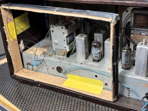
I started this thread a long time ago, it was only my 4th radio restoration. The 49-905 turned out to be missing the broadcast loop antenna. In this set it was one of those that was glued around the inside of the case near the back. At the time I had the FM working OK and for that reason the set became my shop radio. I also had a soft spot for 1949 as its my birth year. I've toyed with trying to fabricate a loop for the set but never got around to it until recently. Just to see if I could make something that would actually pull in stations I put about 20 loops of 30 gauge wire around a cardboard box frame and wired it in. Lo and behold it worked just fine, not there is that much to listen to on AM these days. I may try to make something that's a bit more permanent and closer to the orginal look but for now it will do just fine.
Posts: 18,427
Threads: 622
Joined: Oct 2011
City: Jackson
State, Province, Country: NJ
Bob,
These loops are tuned ciruits with the tuning cap, so the number of tirns should be same as originally.
So, after you made that antenna, do you have your dial in agreement with the input frequency if you try to align it?
People who do not drink, do not smoke, do not eat red meat will one day feel really stupid lying there and dying from nothing.
Posts: 5,584
Threads: 291
Joined: Nov 2012
City: Wilsonville
State, Province, Country: OR
Thanks Mike. So far I was just happy to get clear reception. I’ll have to check the frequency tracking.
Users browsing this thread: 1 Guest(s)
|
|
Recent Posts
|
|
Philco P45-6365 Universal Transformer Instruction Manual
|
| Can anyone guide me to where this may be found?GRG — 03:00 PM |
|
54C Complete Teardown/Rebuild
|
| I don't think that I have encountered a 12Z3 before, curious how it uses one of those but includes a #43, which is a 25 ...Arran — 02:17 PM |
|
HiFi (Chifi) tube amp build - but my own design.
|
| It's the other forum. I'm also in DIY, but mostly read there. Honestly, I kinda jumped into this without much thought to...TV MAN — 10:43 AM |
|
Philco 71 Code 125
|
| Hello,
I am in need of a schematic for this radio. Mine has the three separate circular tube shields and a shadow me...dconant — 08:06 AM |
|
Stromberg Carlson 1500 Squeal
|
| And life just keeps getting more complicated.dconant — 07:57 AM |
|
54C Complete Teardown/Rebuild
|
| Hello Roy,
here is this one
sincerely Richardradiorich — 12:45 AM |
|
54C Complete Teardown/Rebuild
|
| Richard,
Had grabbed it already but thank you just the same. I find myself wanting to find some way to block out the...glyphmon — 12:03 AM |
|
54C Complete Teardown/Rebuild
|
| Hello roy,
here is a link to the schematic .
Sincerely Richardradiorich — 11:54 PM |
|
54C Complete Teardown/Rebuild
|
| Richard,
The Silvertone 2014 also is a transformerless set, so I am incorporating a 1:1 600 ohm audio isolation transfo...glyphmon — 11:37 PM |
|
Preliminary work on wife's Silvertone 2014
|
| Did an alignment today which was interesting. IF alignment went great, almost all was already spot-on. Adjusting on th...glyphmon — 11:35 PM |
|
Who's Online
|
There are currently 1919 online users. [Complete List]
» 1 Member(s) | 1918 Guest(s)
|
|
|

|
 
|







