Posts: 1,531
Threads: 242
Joined: Sep 2012
City: West Bend, Wisconsin
Finally getting around to giving a 41-255 I picked up over 15 years ago the proper attention it deserves, and have a bunch of questions I'm hoping those who are far more knowledgeable than I might know the answers to.
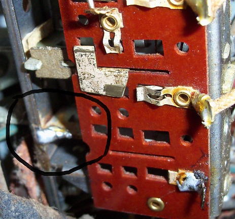
First, it appears that the first pushbutton on the left was originally supposed to be to turn the set on, is that correct? Someone soldered the button lever tight so it cannot be used, and on my set, the first knob on the left is for tone, and the second knob from the left is off/on/volume. I'm thinking this should just have been a volume only pot. Here's a pic of the soldered lever:

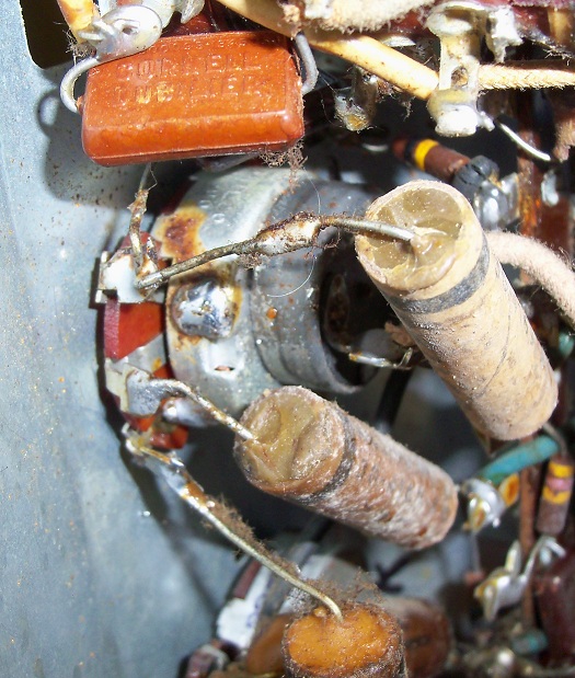
And here's a pic of the off/on/volume switch:

Second, tube talk. This set uses two 7A4 tubes in place of the XXL's that the schematic calls for. Are these suitable replacements?
It also uses a 7C6 in place of the 7B6, and a 7B7 in place of the 7A7. Do these replacements work as well as the tubes that the schematic calls for?
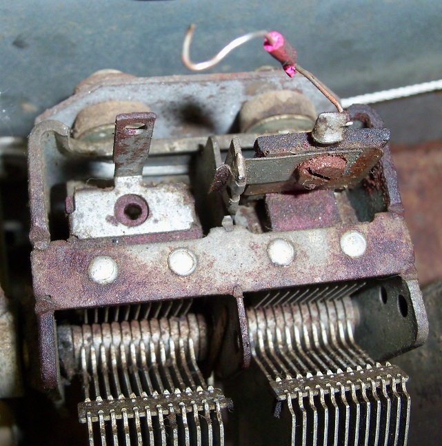
Lastly, I touched the center pin of the volume control with a screwdriver and got loud volume, so I know that part is good, but I can only get the local station faintly at full volume, even with the antenna connected. There is a wire on top of the variable capacitor that wasn't connected to anything:

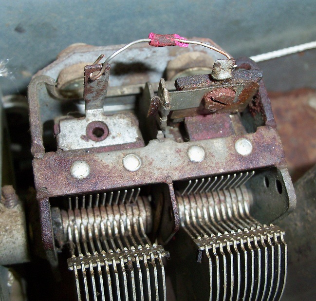
I wasn't getting any sound without it connected. When I connected it to the lug opposite it on top of the variable capacitor, I got the station faintly:

But I think there must be something missing there that I'm not finding on the schematic. Just a plain wire (with that great dried rubber insulation flaking off) can't be all that was connected between there? Should there be a capacitor up there?
I know these probably are dumb questions, but I am just a novice here. Any thoughts, ideas, help would be greatly appreciated!
Greg V.
West Bend, WI
Member WARCI.org
Posts: 13,776
Threads: 580
Joined: Sep 2005
City: Ferdinand
State, Province, Country: Indiana
Greg
1. Yes, the first button on the left originally activate the off-on switch, which was originally mounted on back of the pushbutton assembly, directly behind that first button actuator. The volume control did not have an off-on switch originally.
2. 7A4 is electrically identical to XXL. Some of these are in fact labeled 7A4/XXL. No time right now to comment on the others, I would have to look them up at nj7p.info and compare characteristics.
3. That wire with just a tiny bit of red rubber insulation remaining is, or I should say was, the "gimmick" capacitor. It should be placed through the lug as you did, but it should not be making metal-to-metal contact; the insulation should prevent the wire from actually touching the lug.
Place a bit of heat shrink tubing over that wire and then put it through the lug again - the radio may come to life once you do that.
--
Ron Ramirez
Ferdinand IN
Posts: 1,106
Threads: 88
Joined: Jun 2011
City: Tacoma
State, Province, Country: Washington
Ron,
I haven't been able to access N7JP's tube info site for quite some time. When was the last time you used it? It was always an invaluable resource for me.
I've been using this resource since I lost access to N7JP:
http://www.mif.pg.gda.pl/homepages/frank/vs.html
Posts: 2,128
Threads: 18
Joined: Oct 2008
City: Merrick, Long Island, NY
Link works now, one more step to get to tube data. More neat stuf here anyway. XXL/7A4 was a funny bird anyway.
http://www.nj7p.info/
Posts: 13,776
Threads: 580
Joined: Sep 2005
City: Ferdinand
State, Province, Country: Indiana
This link works for me:
http://www.nj7p.info/Common/Tube/SQL/Tube.php
I think it used to be "nj7p.org" (instead of .info) but that link no longer works.
--
Ron Ramirez
Ferdinand IN
Posts: 13,776
Threads: 580
Joined: Sep 2005
City: Ferdinand
State, Province, Country: Indiana
7C6 is shown as a "preferred" substitute for 7B6, but the characteristics are slightly different, and the 7C6 uses 0.45 A of filament current vs. 0.3 A in the 7B6.
7A7 is a sub for 7B7. 7B7 uses half the filament current as the 7A7 (0.15 A vs. 0.3 A), but the characteristics are otherwise nearly identical.
--
Ron Ramirez
Ferdinand IN
Posts: 1,106
Threads: 88
Joined: Jun 2011
City: Tacoma
State, Province, Country: Washington
Thanks for the new link, Ron. 
Posts: 1,531
Threads: 242
Joined: Sep 2012
City: West Bend, Wisconsin
Thanks so much, Ron, for the help. Sorry for the delay in acknowledging it... a pesky little thing called a job sometimes takes priority over my hobbies 
Thanks to your checking, I think I'm in good shape with the current substitutions, tube wise, and I appreciate the link to check on these in the future. Very handy!
As far as the (now) off/on/volume switch in place of the volume only, I think I'm just going to leave it that way. If it works, I guess it doesn't really matter too much if you have to push a button or twist a knob to turn the set on, to me at least.
I did remove the rest of the crumbling red coating and put a piece of heat shrink around that "gimmick" capacitor, all the way to the exposed end of the wire, and put it back in the lug as shown in the picture above. No metal is touching on the lug now, just the now insulated wire. It didn't really make too much difference, but when I touched the lug that was already soldered tight (see photo above), I got lots of volume. I think the real test will be when I hook up the 3 antenna wires in the cabinet to see how that affects volume and sensitivity. Just waiting for the cabinet to cure after applying a wood treatment to it before I do.
I did notice the speaker was somewhat garbled sounding. Will double check the tubes in the audio output section next and see that makes a difference. Good news is I'm making some progress, and want thank you again for your help!
Greg V.
West Bend, WI
Member WARCI.org
Posts: 1,106
Threads: 88
Joined: Jun 2011
City: Tacoma
State, Province, Country: Washington
If you don't have the cabinet antenna connected, this would definitely be the reason for not having any strong signals. The end of that wire that is soldered to the lug is the antenna section of the tuner, this is why when you touch it, you get a signal. The garble in the audio could well be due to the antenna not being connected. This is because when there is no return path on the antenna input, it creates a very high impedence input, which can pick up hum from the environment. This gets sent down the chain and you hear it in the speaker. Once the antenna is properly connected, and there is a return path (usually through the AGC circuit), this hum will not be there because the input then becomes a lower impedence.
Posts: 1,531
Threads: 242
Joined: Sep 2012
City: West Bend, Wisconsin
Thanks, Brenda. I appreciate your help. I did have a makeshift antenna connected with a gator wire, but because it wasn't a loop, it probably isn't enough. Will try it tomorrow. Time to turn in for the night and dream of Philcos 
Greg V.
West Bend, WI
Member WARCI.org
Users browsing this thread: 1 Guest(s)
|
|
Recent Posts
|
|
philco predicta
|
| I found that where I have the 140v B+ there is 50v and the tuner receives 235v through the orange cablecgl18 — 04:14 PM |
|
Philco 91 code 221
|
| Chassis grounds thru rivets is another good place to look. Oh and the stator screws on the tuning cap where the leads at...Radioroslyn — 08:11 AM |
|
Philco 91 code 221
|
| Dirty tube pins and socket, cold solder joint, stray tiny strand of wire, clean the entire area around the oscillator tu...RodB — 08:43 PM |
|
Philco 91 code 221
|
| I have been restoring one of these sets and switched it on yesterday. It didn't exactly spring into life, but after a co...Philconut — 08:26 PM |
|
Philco 50-925 antenna connections
|
| That's super. Glad to hear you figured it out. Paul.Paul Philco322 — 11:11 AM |
|
Philco 50-925 antenna connections
|
| Hello Keith,
great news !!
Sincerely Richardradiorich — 02:14 AM |
|
Philco 50-925 antenna connections
|
| Finally, got the antenna fixed (repaired some broken wires) and have the radio playing. I've got four different schemat...keith49vj3 — 09:38 PM |
|
1949 Motorola 5A9M
|
| Bob, Nice radio. I’ve not seen one before. Keep us updated!Joe Rossi — 07:56 PM |
|
Phioco 90 Power Transformer Wire Colors
|
| Thanks for adding that information.klondike98 — 06:09 PM |
|
Phioco 90 Power Transformer Wire Colors
|
| Although I have used this site as a resource for a number of years this is my first post. I am restoring a Model 90 si...vincer — 05:02 PM |
|
Who's Online
|
There are currently 1509 online users. [Complete List]
» 1 Member(s) | 1508 Guest(s)
|
|
|

|
 
|


![[-] [-]](https://philcoradio.com/phorum/images/bootbb/collapse.png)


