Posts: 4,106
Threads: 310
Joined: Nov 2013
City: Kings Park NY
So I am just finishing the chassis and there are 3 issues.
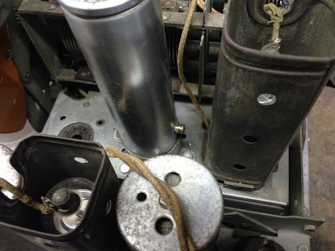
1. I replaced a 16 mfd 450v wet Ecap and want to make sure I am doing it right. There is one wire going underneath the chassis (pos) and the other wire (neg) goes to the can? I was told that the neg does not go to chassis but to the can itself. I affixed it with a brass screw. See picture..
Is that correct?

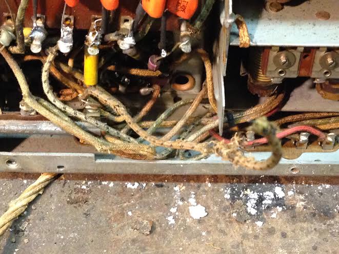
2. I have a floating wire from a terminal strip to nowhere. It is on the terminal strip with the yellow resistor. When I first saw it it was hanging near the Ecap #66 which was replaced in the past and was all taped up.
I cant seem to find any missing connection but as we know I cant read the schematic that well.
http://www.nostalgiaair.org/PagesByModel...013216.pdf

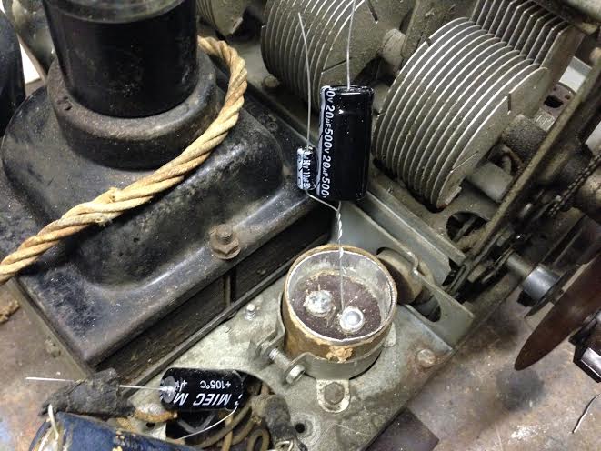
3. I replaced the Ecap that is 69 and the schematic says 20 mfd but the can says 20 mfd 450v and 10 mfd 50v. there are only 2 terminals so how do I affix these? paralell or leave out the 50v Ecap?

Thanks
Kirk
Times I have been electrocuted in 2021
As of 1/01/2021
AC: 4 DC: 1
Last year: 6
(This post was last modified: 02-19-2014, 01:06 PM by OldRestorer.)
Posts: 674
Threads: 146
Joined: Jun 2011
City: Elko,MN.
OOFTA<
Your not attaching those electrolitics to the top side of the can are you?
murf
Posts: 16,569
Threads: 574
Joined: Oct 2011
City: Jackson
State, Province, Country: NJ
Kirk
You gotta be sh...me, man. Is this how you do it? Or...??????
Posts: 1,562
Threads: 56
Joined: Nov 2008
City: Sedona, AZ/Placentia/CA
Oh my Kirk where does one start to answering these questions? Well, a posted schematic:
http://www.nostalgiaair.org/PagesByModel...013216.pdf
Please blow this up and look at items 66A (10mfd) and 66B (18mfd) The two caps you have selected will be fine. Please also note that the can you cut off for installation has a cardboard tube around the base to isolate the can from the clamp which is screwed to the chassis (hence ground).
Looking at the underside of that can there should be a tab attached to the base of the can, that tab and the two "internal" connections in the can represent the three leads you now have as shown.
Tricky and I may be wrong but the negative of the 18mfd and the positive of the 10 mfd should be attached to whatever attachment there was on the underside of the cap going to its metal base. Again this tab should not show direct (zero) resistance to the chassis.
This leaves the 10mfd negative and the 18mfd positive going to the two feedthrough connections. You will need to trace which goes to which based on following the schematic. This is assuming you have not removed the wires from the bottom of the cap.
I hope this helps. Hint, the 10mfd negative will go to chassis ground.
I will leave the other questions to someone with more patience and understanding.
Good luck! Jerry
A friend in need is a pest! Bill Slee ca 1970.
(This post was last modified: 02-19-2014, 03:55 PM by jerryhawthorne.)
Posts: 4,106
Threads: 310
Joined: Nov 2013
City: Kings Park NY
This is what I was told:
The one wire would be the positive; the negative is the metal can itself which is often bonded to chassis ground via the mounting tab soldered to the chassis. (Occasionally it's insulated from chassis and has a separate negative lead.) Mount the negative to the outside aluminum shell!!! The capacitor negative may be floating from the chassis, depending on if there are insulating washers on the mounting nut or not. The center rod through the rubber insulator at the base is the positive connection. It is usually aluminum, so you will have to replace it with a brass screw or similar.
Thanks for the info but I will figure it out somehow, don't want to frustrate anyone.
Times I have been electrocuted in 2021
As of 1/01/2021
AC: 4 DC: 1
Last year: 6
Posts: 16,569
Threads: 574
Joined: Oct 2011
City: Jackson
State, Province, Country: NJ
I never use either the rod or the can as electrodes when I rebuild: you cannot (normally) solder to aluminum, and the rod could also be aluminum.
I simply let the wires out of the bottom. Often times if the wire is thick and stubby enough it still can be used as a soldering post (as the rod is often used that way) and the negative could be soldered to a ground post or to an insulated negative post usually provided originally when the can is not grounded (like in 70 or 90).
In this particular (shown in the photo) case you have output contacts that are riveted with negative case: when this is the case I drill through each rivet and also drill through the base; then let the positive wires from the caps out through the rivet (marking them so I don't forget which is which when closing in case the capacitances are equal and you cannot tell which is which), and then let the common negative through the hole in the base.
This has another benefit in case the can was grounded - you simply put the negative wire you let out through that third hole under the clamp and voila - you have a grounded can cap.
Posts: 1,562
Threads: 56
Joined: Nov 2008
City: Sedona, AZ/Placentia/CA
Kirk, your understanding in post one is spot on for that cap. Simple single cap in a can that is tied to the chassis. Positive to the center conductor, negative to the can. What most of us have a problem with is the screw in the side of the can to presumably tied the ground there. It is not necessary, required a lot of effort and will not provide a good ground. It was tied to the top of the can which has no great connection (compression fit perhaps) to the base of the can.
Soooo much easier to drill a small hole in the base and run the negative wire into that and tie it to the chassis. At least under one of the nuts holding the clamp of cap in place or a local chassis ground connection. As for the positive, drill a small hole next to that terminal and feed through to tighten around or solder to that terminal. If it is a solder type go for that. If it is nut type, wrap it around it. As Mike has indicated, soldering just doesn't work on the can inside terminals as they are typically aluminium and were spot welded to the wiring of the original caps.
For your two cap can, do the same thing, three small holes in the base to feed the wires in
two close to the riveted tabs and one close to the outside for the grounds. Sorry if we are unclear but tough working with such a talented cabinet person and well, new to the electronics. Wish you were about 2000 miles closer I could help you with the electrical and you could help me with finishing.
Best Jerry
A friend in need is a pest! Bill Slee ca 1970.
(This post was last modified: 02-19-2014, 07:00 PM by jerryhawthorne.)
Posts: 16,569
Threads: 574
Joined: Oct 2011
City: Jackson
State, Province, Country: NJ
Come summer we could do the expertise exchange  between the beer. In the winter it is too darn uncomfortable to work in the garage.
Posts: 1,562
Threads: 56
Joined: Nov 2008
City: Sedona, AZ/Placentia/CA
See Kirk, you have two offers. Highs in the 70s here now!
Mike is much smarter! But you will have to wait (also closer).
Best, Jerry
A friend in need is a pest! Bill Slee ca 1970.
Posts: 2,575
Threads: 337
Joined: Jun 2013
City: lawrenceville nj
Woohoo morz doing electronics 101 course sign me up too I'll bring the radios and jd
Posts: 1,562
Threads: 56
Joined: Nov 2008
City: Sedona, AZ/Placentia/CA
Kirk, my bad looking at the schematic. I should have listed the double cap as 66 and 66A. As for the first picture in your post of the cap with the screw on the side, I believe that is 69, I made the assumption due the picture that didn't show any insulation between the can and the clamp that the case went to ground. According to the schematic the case of that cap should go to the center tap of the high voltage winding of the transformer electrically to the same place the two wired together caps ends of 66 and 66A go to. Does that make sense? The only reason I can think of is if the single cap (69) has two connectors out the bottom one for positive and one for negative. All I have seen use the can as negative. Is there a cardboard insulator between that clamp and the can that doesn't show?
Sorry if I'm confusing.
Best, Jerry
PS: Check your PM
A friend in need is a pest! Bill Slee ca 1970.
(This post was last modified: 02-19-2014, 10:25 PM by jerryhawthorne.)
Users browsing this thread:
|
|
Recent Posts
|
|
[split] New member...
|
| You may have to start further back with your signal injection at the IF signal grid, then tune the second IF transformer...RodB — 10:28 AM |
|
[split] New member...
|
| Well, with the replacement tuning assembly, I have finally put the unit back together and aligned the dial. The first s...HowardWoodard — 01:01 AM |
|
Philco Model 16 wiring question
|
| Well, finding a short is easy.
Like I said, disconnect the transformer's secondary windings and see if it persists.
If...morzh — 09:48 PM |
|
Restoring Philco 96
|
| Nice one!Stan the Man — 09:37 PM |
|
Restoring Philco 96
|
| I have eventually replaced the speaker and shot the video, which only shows the upper part of the dial as the hum is ver...morzh — 09:24 PM |
|
Rogers Majestic R-646
|
| Kinda weird to see both open
Nothing weird if you remember that this radio is about 100 years old :)Vlad95 — 07:49 PM |
|
Philco 42-345 Restoration/Repair
|
| I believe I'm making progress, resistors have been rechecked and corrected, removed that ugly blue capacitor and more wi...osanders0311 — 07:38 PM |
|
Philco Model 16 wiring question
|
| Thanks Morzh
Yes I recapped everything and replaced almost all the resistors as well. I redid #99 with .015 safety ca...bobclausen — 07:11 PM |
|
Philco Model 16 wiring question
|
| Well...pull out every single load of the transformer. For every winding.
Unsolder if needed.
Then re-do your dim bulb....morzh — 07:02 PM |
|
Rogers Majestic R-646
|
| Kinda weird to see both open, but once you get it up and running, really pay attention to your sound. Listen for loud cr...TV MAN — 06:59 PM |
|
Who's Online
|
| There are currently no members online. |

|
 
|


![[-] [-]](https://philcoradio.com/phorum/images/bootbb/collapse.png)


