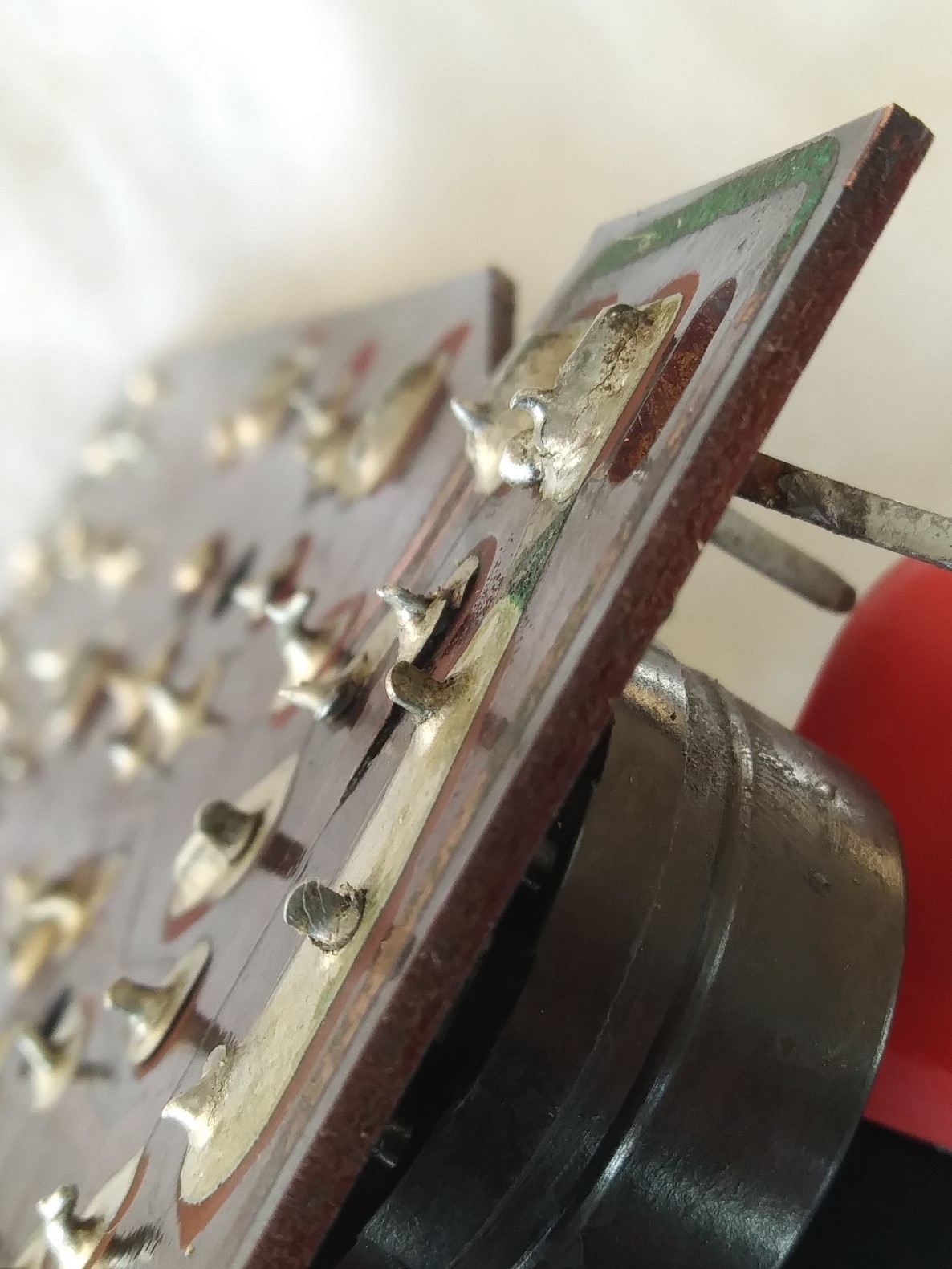
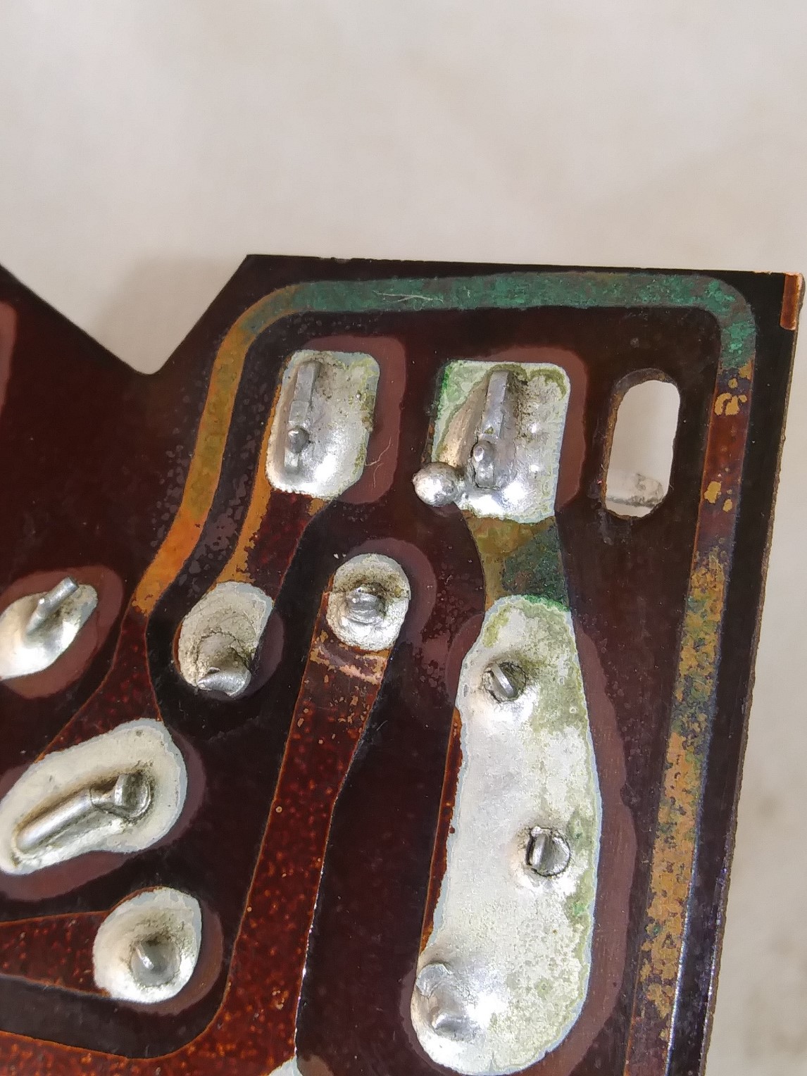
Philco Predicta board lifted trace and trace corrosion.
Posts: 2
Threads: 1
Joined: Mar 2022
City: Chilliwackv
State, Province, Country: BC
Hello i am new to this forum and a relatively newcomer to the hobby of tv repair so I work slowly but surely  . I'm working on a Philco Continental with the 10L43a board. Removed the board from the chassis and discovered this lifted trace under the Horizontal output tube as well as the corrosion on the B+ trace line. Both the lifted trace and corroded B+ test good for continuity. I will be replacing the Horizontal tube base. Looking for advice on how to re-attach the lifted trace and and deal with the green corrosion Thank you


Posts: 1,578
Threads: 98
Joined: May 2008
City: Omak
State, Province, Country: WA
hello Jas,
First all Do you have a solder sucker or solder wick I would try to remove some of that soler then clean the area and try soldering some new solder also what you are using to soler with? myself I would use my temperature soldering iron.
Too much heat will cause issues also not enough heat will also cause issues .
Sincerely Richard
Posts: 2
Threads: 1
Joined: Mar 2022
City: Chilliwackv
State, Province, Country: BC
Hello thank you for this advice. I'm replacing the tube base and try the approach you mention. This was the condition of the board when I got this set. I have one temperature controlled iron that I'll use for this and be careful of the heat.. Thank you
Posts: 1,578
Threads: 98
Joined: May 2008
City: Omak
State, Province, Country: WA
Hello Jas,
Good luck !
Sincerely Richard
Posts: 1,002
Threads: 9
Joined: Jul 2020
City: Greenlawn
State, Province, Country: NY
Hi Jas,
One of my more favorite solder suckers used to be available from Radio Shack. Was an Iron that instead of the usual tip, had a nozzle, stem and bulb. It worked well. One should be careful of overheating, but IMHO, it worked better than the various de-solering tools(Solderwick, Soldavac (Manual spring loaded syringe that the user cocks, puts against hot joint and pulls trigger), etc. Best is a pro de-soldering station, but these cost lotza bux. A metal brush may take care of the corrosion. Re-tin the trace.
Judging from the pix, there are a lot of cold solder joints on that socket. Why are you replacing the socket? Is there obvious damage? If the issue is intermittent operation, check the condition of all solder joints on the socket. The picture seems to show cracks in several of the solder joints that would break the connection.
On old boards, I will run some 18 gauge solid insulated wire over the trace from point to point, following and paralleling the trace. For example, from the heater pin to the next heater pin, transformer lead, ground, etc., particularly for the heater, cathode and plate connections that handle large current. The horizontal output tube may draw more current than any other circuit in this TV.
It is also common on TVs of this vintage, where the PC Board mounts on tabs bent up from the chassis, that the solder connections between these boards and the chassis are also poor. if this tab is providing chassis ground to the board, failure of the solder joint will cause all sorts of problems. There is often more than one of these chassis grounds on the same board, and often, they are not connected to each other. Therefore all of these joints must be good. It is a good idea to consider point to point wire connections for these grounds also.
I have fixed many a TV and other electronic device by reheating cold joints, adding point to point connections, etc.
Hope this helps.
John "MrFixr"
"Do Justly, love Mercy and walk humbly with your God"- Micah 6:8
Best Regards,
MrFixr55
(This post was last modified: 04-08-2022, 04:54 PM by MrFixr55.)
Posts: 1,130
Threads: 79
Joined: Jan 2014
City: Annapolis, IL
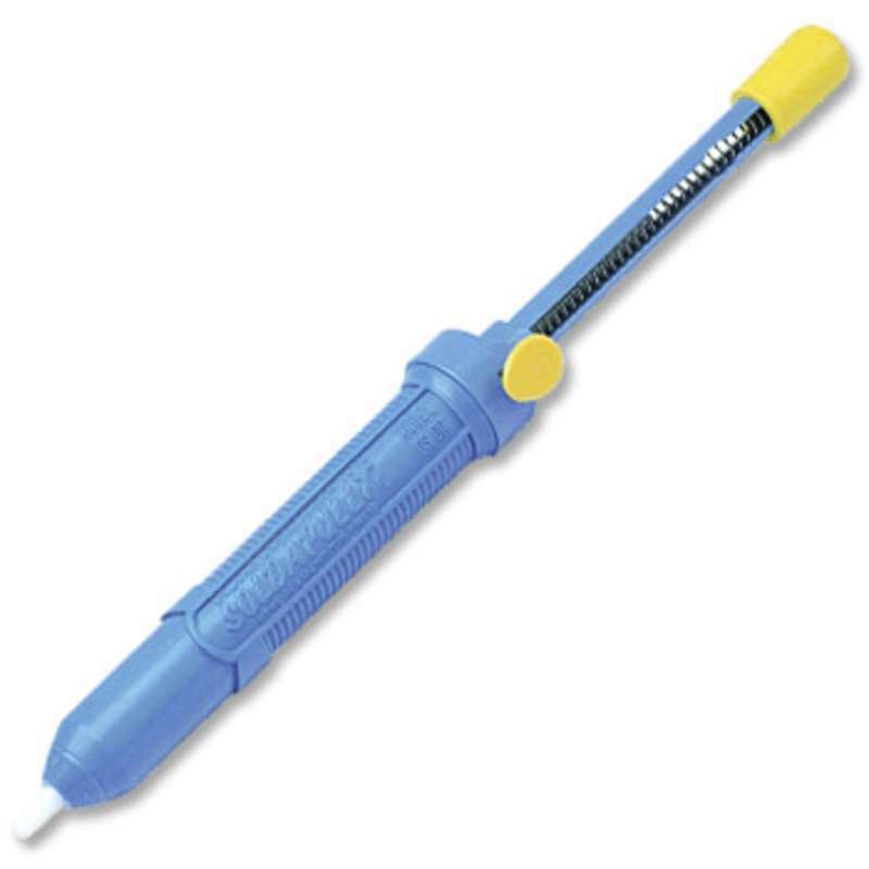
One of the best hand held desoldering tools is one of the Soldapullit (or something like that lol), it's a big blue solder sucker, and its kinda like holding a telephone pole to desolder, but it seems like it works a lot better than some of the smaller ones. A desoldering iron also works, but I dont think quite as well. Solderwick works great - IF you happen to get a good batch. I used the last of my Radio Shack supply, and the newer stuff is worthless. I noted as John mentioned there are a lot of cracked (cold) solder joints around the socket area. I too have fixed many a TV over the years by resoldering those, usually around heat producing components like power transistors, larger resistors, PC mounted flybacks, etc. You can bridge the bad traces with wire. May not be pretty but will work.

If I could find the place called "Somewhere", I could find "Anything" 
Tim
Jesus cried out and said, "Whoever believes in me , believes not in me but in him who sent me" John 12:44
(This post was last modified: 04-17-2022, 09:35 PM by TV MAN.)
Posts: 1,578
Threads: 98
Joined: May 2008
City: Omak
State, Province, Country: WA
Mr fixit,
yes I am ordering myself a new desoldering station but yes I use to have that radioshack unit you talk about .
Sincerely Richard
Users browsing this thread: 1 Guest(s)
|
|
Recent Posts
|
|
Jackson 715 not working
|
| Now that you posted the schematic, I don't know why that Sprague electrolytic cap is across the meter, as it is not indi...MrFixr55 — 05:51 PM |
|
HiFi (Chifi) tube amp build - but my own design.
|
| What may be lacking in the PP Tube amps may be the 2nd harmonics, which some, especially RCA back in the day called &quo...MrFixr55 — 05:32 PM |
|
Jackson 715 not working
|
| Usually in an emission tester, the tube under test is measured as if it were a diode. So, some testers connect all the g...RodB — 04:17 PM |
|
Restoring Philco 37-604C
|
| Yep. F5 is green, D5 is Red.
Red is Bad.
Green is Clean.morzh — 01:30 PM |
|
Jackson 715 not working
|
| I did start to do that but I stalled out because I could not figure out how the grid and plate get voltage. In this diag...daveone23 — 11:52 AM |
|
Restoring Philco 37-604C
|
| (Insert Homer Simpson "DOPF" Here.)
When all fails, look at the can. Took the Ron Ramirez advice, red Caig D...MrFixr55 — 09:23 AM |
|
Philco 91 Speaker Replacement
|
| From your text I am not sure if you intend to use the existing speaker with a resistor instead of the field coil.
It wo...morzh — 08:44 AM |
|
Philco 91 Speaker Replacement
|
| My field coil is bad. I am still hoping to find an original, but if I can't I will go with a fitting Philco speaker, 125...dconant — 08:34 AM |
|
Philco 91 Speaker Replacement
|
| As Rod said, it is OK to use a fitting speaker, and then look for an original one.
If you buy a Hammond 125 output tr...morzh — 08:15 AM |
|
Philco 91 Speaker Replacement
|
| Yes, I often have to substitute, then keep an eye out for an original. In the meantime, the radio is working and being e...RodB — 08:02 AM |
|
Who's Online
|
| There are currently no members online. |

|
 
|
 . I'm working on a Philco Continental with the 10L43a board. Removed the board from the chassis and discovered this lifted trace under the Horizontal output tube as well as the corrosion on the B+ trace line. Both the lifted trace and corroded B+ test good for continuity. I will be replacing the Horizontal tube base. Looking for advice on how to re-attach the lifted trace and and deal with the green corrosion Thank you


![[-] [-]](https://philcoradio.com/phorum/images/bootbb/collapse.png)


