Starting 37-116 Deluxe Restoration
Posts: 126
Threads: 13
Joined: Sep 2013
City: Milwaukee, Wisconsin
I took a look at it this morning, and determined the only possible way to get those two caps was to separate the band switch dividers from the top of the RF chassis.doing so is the only way to get these caps out from inside the coils. here is the view once you separate the top of the RF chassis from the band switch dividers. This is the only way these can come out.
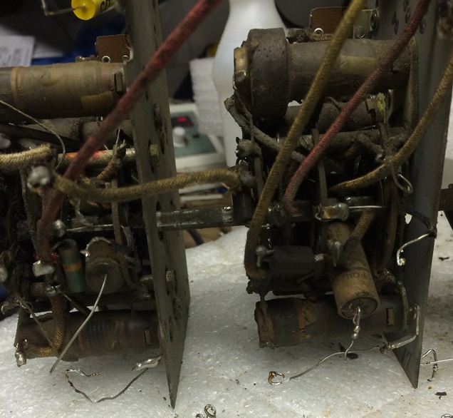
But even then, it's still a bear to get to the top lead. On one I was able to get my smallest pair of side cutters in there between a couple coils. but just barely. The other I had to take an exacto knife and slowly hack away at the lead till it cut it. Then I could carefully get my iron in between the coils to get to the new ones soldered in place.
I buttoned the RF chassis back up, put it back in the main chassis, and reconnected the wiring. Before putting the rectifier in, I went through again and made sure all the filaments were reading correctly. I put just the rectifier in, and put my DMM across the filter caps and transformer CT. I slowly brought it up on the variac, and watched B+ as I brought it up. Also kept an eye on my ammeter. Everything looked good, so I put all the tubes and shields back in. Brought it up slowly again on the variac, B+ was holding steady around 360v (schematic says 370), and it was drawing about 1.1A through the variac.
But I don't get anything on any of the bands. Can't tell what band I'm on as i have thethe dial and band mask off. Using my signal generator, I set it to 470 and injected the signal into the grid cap of the mixer. I can hear it accross all bands. I then set my sig gen to 600, and injected to terminal #1 on the back. I could pick it up with the band switch all the way counter clockwise, and in a certain spot on the tuning cap. But its fairly quiet, and the volume doesn't increase until I get near the upper end of the volume pot. Then it starts getting louder.
Normally at this point, I'd go around and check voltages on the tubes. But that is going to be impossible on any in the RF chassis. So I'm at a loss right now.
Posts: 126
Threads: 13
Joined: Sep 2013
City: Milwaukee, Wisconsin
While waiting for some help on the electrical issues (I know I need to provide more symptoms and voltage readings for anyone to start giving suggestions - I just needed to walk away from the electrical side of the radio after such a let down), I decided to tackle some mechanical issues.
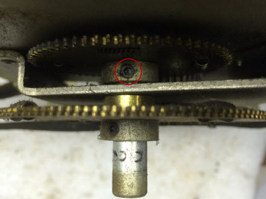
The first was the dial hub that was not always rotating with the vernier drive and tuning capacitor. I was getting ready to disassemble the veneer drive to see if there was an issue in there, when I looked down between the metal plates. i noticed this seemed to be the area where the slipping was occurring. I stuck an allen wrench in this set screw, and sure enough, i was able to tighten it a little. Now the dial hub is moving with the veneer drive.
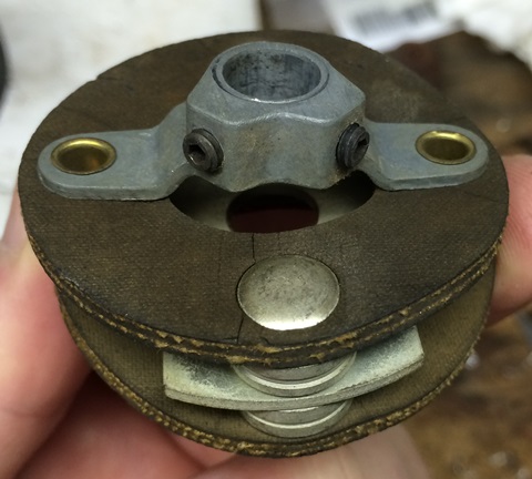
The second issue was to tackle the old dried up flex coupling. The rubber was stiff and cracking:
I followed Mondial's guide on the Phorum on creating a new one. Minus the saving the brass rivets, cutting new rivets on a lathe, and using a punch to cut the holes. I opted for a couple #8 screws (3/8" to replace the brass eyelets, 1" to replace the steel rivets), washers, and nuts. I just used the Dremel to grind away the lip on one end of the rivit, and they popped out with a punch. Then I traced out a 2" circle and in it, a 7/8" circle. I cut the 2" circle with scissors, and the inner circle with an exacto knife. Then I drilled the screw/rivet holes with a 3/16" drill bit.
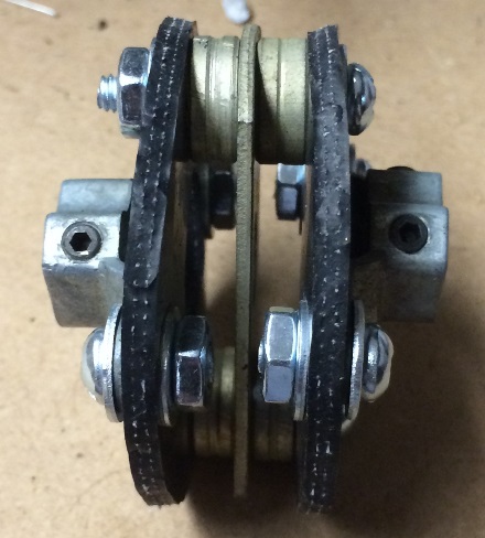
It's not nearly as pretty as Mondial's, but it gets the job done witht he tools and skills I had at hand.
So, now back to collecting readings and symptoms. At least now I can reattach the tower and mask/dial scales, so I can see what I'm tuning to.
Posts: 126
Threads: 13
Joined: Sep 2013
City: Milwaukee, Wisconsin
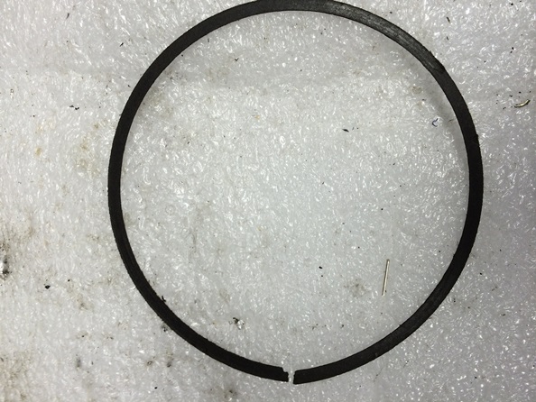
While going through the dial parts I removed, I noticed one of the paper like rings was torn by the notch. Any ideas on the best way to fix the rip? Maybe a real small spot of super glue?
Posts: 16,562
Threads: 573
Joined: Oct 2011
City: Jackson
State, Province, Country: NJ
Not even sure you need it. I just put the dial in the way it came from Daze, the paper ring was in pieces.
Posts: 126
Threads: 13
Joined: Sep 2013
City: Milwaukee, Wisconsin
(10-14-2014, 07:31 PM)morzh Wrote: Not even sure you need it. I just put the dial in the way it came from Daze, the paper ring was in pieces.
Yeah, I'm not sure what purpose it serves. As long as mine is in fairly good shape, I figure I'll keep it in place. I took a closer look at the material. It kind of reminds me of speaker material. So I took some Sobo fabric glue that I use to repair tears in cones, and used it to put this ring back together.
I built a stand (my existing stand wouldn't accommodate this chassis) so I can power the chassis up and run some checks. The plate on the RF tube had no voltage. I pulled the RF chassis again (which is still a pain, but it gets easier once you've pulled it once and you know what you are doing) and checked it out. Turns out when I disassembled the RF chassis, I disconnected that wire and didn't reconnect it to pin 3 on the socket. That wire carries B+ to the tube.
However, the radio behavior hasn't changed. I still have a low constant tone when I inject at the antenna terminal for about 3/4 of the volume. Then it gets louder on the last 1/4 turn of the volume knob. I noticed that the sound coming out of the speaker when injecting RF into the antenna (and I have the volume up in that last 1/4 turn where it starts getting louder) the tone is warbling/distorted. Which I think is a sign of oscillation, right?
I just got a signal tracer, so I figured out now might be a good time to try it out. I used the signal tracer, and the tone sounds clear at the antenna terminal, the RF grid cap, the mixer grid cap, and the 1st IF grid cap. It sounds a little distorted then at the 2nd IF grid cap. So I went back to the 1st IF plate and it sounds a little distorted there too. So
I'm guessing the distortion is being introduced around the 1st IF. But that is as far as I know how to check. I briefly looked at all the connections to the 1st IF, and everything seems good. The plate voltage is a little low (188-195, usually a little lower on 2nd than 1st) as it should be around 220. I know DMM's measure differently due to the input resistance. So I'm not sure if this is actually relevant.
I also worked backward form the speaker to try and figure out my volume issue by injecting an audio signal at various points:
Radio off, pin 3/plate of both output tubes - I can hear a faint tone in the speaker. For the rest, the radio is on.
Driver pins 3 & 4 (tied together) plate & screen - I get a slightly louder tone than I did with the above test.
Driver pin 5/grid - I get a much louder tone.
1st Audio pin 3/plate - I get about the same tone as the driver grid gave me.
1st audio pin 5/grid - I get a tone that is controlled with the volume knob on the radio. But it seems to be acting funny:
From low to about 1/4 turn, the tone gets louder.
From 1/4 to 1/2, it starts getting quieter.
From 1/2 to 3/4 , it gets louder again.
I'm wondering if something is coming through the volume pot that is stomping on my signal somehow. To rule out the volume pot being an issue, I did some checks on that.
If I move my audio signal to the "top" of the wiper, I see the same behavior as with the radio - low constant tone for about 3/4 of the volume. Then it gets louder on the last 1/4 turn of the volume knob.
I ohmed out the the outer terminals on the pot, I get a little over 1.7M. Then I tested wiper to ground/chassis on the volume control. All the way low I see 22 ohms. as I turn it to the maximum, the resistance steadily climbs. At 1/2 way its about 640k. Although, something odd does happen around 3/4 of the way. The resistance pauses briefly at about 700k or so. It just briefly keeps reading that as you turn it, then it starts increasing again to 1.7M at the max.
After staring at it for a while, I think i figured out that brief pause in resistance changing. This is a 4 terminal pot. There is a tap on the back that goes to R103 and the tone caps. If I measure that tap to ground, I get 700k. So that pause must be where the wiper is going over the tap. So I'm pretty confident that the pot is good and doing what it should. But something else seems to be suppressing the signal.
If anyone has any ideas on troubleshooting the distortion and/or the volume issue, I'm all ears.
Posts: 16,562
Threads: 573
Joined: Oct 2011
City: Jackson
State, Province, Country: NJ
You are saying you are powering now.
Have you finished the recap?
And all else that should be done prior to it? (tube testing, what not?)
Posts: 126
Threads: 13
Joined: Sep 2013
City: Milwaukee, Wisconsin
(10-17-2014, 03:56 PM)morzh Wrote: You are saying you are powering now.
Have you finished the recap?
And all else that should be done prior to it? (tube testing, what not?)
Yes. I finished the recap Monday afternoon. All caps replaced except for the mica's up in the RF chassis. I tested all tubes on my Hickok 533A when I first got the radio. All were good except two tested a little weak on the Hickok. I then tested those two on my Weston 981-1, and they tested good there. I tend to trust the Weston a little more than the Hickok anyway. Although with the issues I was having, I did swap one of them (one of the like 6 6k7's) with an NOS one. No improvement. Last night I also took the dremel wire wheel to the shields and bases. No improvement.
Posts: 126
Threads: 13
Joined: Sep 2013
City: Milwaukee, Wisconsin
I did some more tracing and injecting AF, and It just seemed like the issue was somewhere between the RF and audio sections. Which pretty means the volume pot.
I noticed that changing tone controls never seemed to affect what little volume I was pulling out to the speaker. So I checked that section. Seemed ok. Then I disconnected the tone circuit from the pot, no change. Then I disconnected the whole pot. I grabbed a spare pot I had laying around (modern one form a different project) and put it in circuit with alligator clips. Worked perfect.
So I clearly have something going on with the volume pot. Which is sort of odd, since it seemed to be ohming out correctly while it was in the radio. And it appeared to work correctly at the seller's house. I'm hoping this can just be cleaned somehow, as this pot is made of unobtanium. It has a slot cut in the shaft for an extended rod to fit in, plus its a 4 tap.
I took it out, and disassembled the pot. Here is what I found:
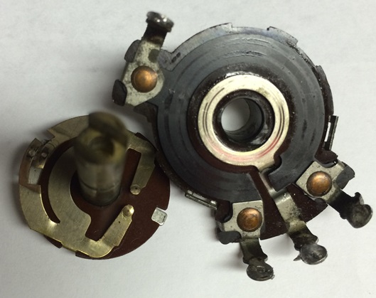
While disassembled, I checked the terminals with my DMM. From outer to outer I get 2.15M, which is right per the schematic. From the "top" leg where the signal comes in to the tone leg, 1.6M. From the ground leg to the tone leg it's 1.1M. So that seems to be correct. From the wiper leg, I have no continuity to any other leg, and have continuity to the brass ring. You can see tracks in the black (carbon?) material from where the wiper made contact. I'm really hoping just cleaning this up will fix it, as it seems to be ohming out correctly.
So, is this fixable/cleanable? And if so, what is the best way (I know I'm opening up a can of worms as everyone has a preferred method and I could get 30 different answers)? I have Dexot D5 and F100 at my disposal. Probably some CRC QD cleaner laying around somewhere. And both 70% and 91% isopropyl alcohol. I'm assuming D5 could be used on a Q tip in the metal pieces. But what is the best way to clean the resistance track?
Posts: 16,562
Threads: 573
Joined: Oct 2011
City: Jackson
State, Province, Country: NJ
Clean it, bend it a little (gently).
Deoxit helps.
Posts: 1,114
Threads: 14
Joined: Feb 2013
City: Irvington, NY
It looks like the wipers have cut a track right through the resistance layer. This is pretty typical of pots which have seen a lot of use.
If cleaning does not help, you can carefully bend each wiper so that it sweeps out a slightly larger or smaller diameter, placing it on an unworn section of the resistance element.
Posts: 126
Threads: 13
Joined: Sep 2013
City: Milwaukee, Wisconsin
OK, I'm completely stumped now. I cleaned the pot out with a little bit of D5, and some F100. Tested it with a DMM, the resistance moved smoothly and physically the pot feels incredibly smooth. Before installing it in the radio, I hooked it up between the audio output on my sig gen, and my sig tracer. It controlled the volume perfectly. Reinstalled it, same behavior out of the radio, low to no volume. I temporarily put in the new pot again that had worked for me before, and that no longer gives me any volume.
So I hooked up the audio signal coming into the radio's pot, and instead of hooking up the wiper to the audio tube, I connected it to my tracer probe. It controls the volume perfectly out of the tracer's speaker. And I can get really good volume out of the tracer too.
Then I did the reverse. Disconnected the the audio line coming out of the 3rd IF and hooked up my sig gen audio output instead to the radio pot, and hooked the wiper up to the audio tube. I can control the volume of the audio signal out of my generator quite well our of the radio's speaker with the volume pot.
It seems like independently the RF and audio sections work great. But as soon as you connect them together, you get nothing. I've cleared both sections, and cleared the pot it self. But they just don't want to play nice together. I just don't get it.
Posts: 126
Threads: 13
Joined: Sep 2013
City: Milwaukee, Wisconsin
The more I test things, the pot doesn't work correctly when I feed the AF from the gen into the radio's audio/amp section. Basically for lower 3/4 of the volume knob I really don't hear anything until I get to the upper 1/4 of the pot.
But if I use the RF signal from the radio into the pot, and feed the signal to my tracer, the pot controls the volume all the way through like it should. So maybe the audio section is t clear after all.
I can also faintly hear the station I have tuned out of the radio speaker, even though nothing is feeding the audio section. Have to put your ear right up to it, but you can hear it. Not sure if it's just picking it up inductively, or if that's tied to my problem.
Posts: 126
Threads: 13
Joined: Sep 2013
City: Milwaukee, Wisconsin
OK, I think I'm on to something in the audio section. I have the pot in place, and wired back up with alligator jumpers. The plate voltage on the audio tube is 199v, and the schematic calls for 90v. I traced all the components where the plate ties into B+, everything seems good. It doesn't list a voltage for the grid, but I'm seeing -20.7 on the audio grid.
A few other voltages are off, but not all of these are in the audio section. not sure if the same issue causing my plate voltage to be high on the audio tube is causing these discrepancies as well.
Driver plate and screen: 183.1, s/b 225
Driver grid: -5.4, s/b 10
Magnetic Tuning plate: 195, s/b 230 (I flipped the magnetic tuning switch, didn't change the voltage)
1st IF plate: 192, s/b 220
2nd IF plate: 186, s/b 220
Also, the grid voltage on the output tubes is -59, but according to the schematic it should be +58. Not sure if that is just a misprint and it should be negative, or another symptom. All the other voltages I checked seemed to be +/- 15v or so from the schematic.
Any ideas?
Posts: 16,562
Threads: 573
Joined: Oct 2011
City: Jackson
State, Province, Country: NJ
Nick,
if your other pot that gave you volume no longer works, it is then posibly not the pot, unless the other pot is bad also.
First test: disconnect the pot fully, connect the 1st Audio input (cap 101) that went to the pot's wiper to the 2nd Det output (cap 74) that went to the pot's top pin.
That should give you full unattenuated volume.
See if this works.
PS. I am not sure why it should be positive on the grids. From the sch it should be negative to the chassis. Grids are pulled to the B-, and cathodes to Chassis, and chassis is above the B-, so Cathodes (filaments) have to be negative .
Posts: 126
Threads: 13
Joined: Sep 2013
City: Milwaukee, Wisconsin
(10-18-2014, 07:18 PM)morzh Wrote: Nick,
if your other pot that gave you volume no longer works, it is then posibly not the pot, unless the other pot is bad also.
First test: disconnect the pot fully, connect the 1st Audio input (cap 101) that went to the pot's wiper to the 2nd Det output (cap 74) that went to the pot's top pin.
That should give you full unattenuated volume.
See if this works.
PS. I am not sure why it should be positive on the grids. From the sch it should be negative to the chassis. Grids are pulled to the B-, and cathodes to Chassis, and chassis is above the B-, so Cathodes (filaments) have to be negative .
I'm pretty confident both pots are working correctly, based on using them to feem the signal tracer. They woirk as expected.
Connecting the two caps together just gives me a whole lot of crackles and pops. Something else is wrong in the audio stage causing the 1st audio 6J5 to have double the plate voltage.
Users browsing this thread: 1 Guest(s)
|
|
Recent Posts
|
|
Philco Model 16 wiring question
|
| Measure the voltages first, just in case.morzh — 02:19 PM |
|
1949 Motorola 5A9M
|
| Haven't thought of Burgess batteries in a while Mr. Fixer. Boston Edison always used Burgess in their Bright Star yellow...Paul Philco322 — 02:17 PM |
|
1949 Motorola 5A9M
|
| Thanks Sam. I'll let you know. I can probably scare some up from the local radio club.klondike98 — 02:07 PM |
|
Philco 89 Code 123 Osc Coil
|
| Hello,
I thought I would post my findings on my bad oscillator tickler coil. There were 27 turns on the outer coil b...dconant — 12:38 PM |
|
Philco Model 16 wiring question
|
| Thanks Morzh. So it appears I did wire it incorrectly and I have to switch the wires between pins 2 and 4.bobclausen — 09:24 AM |
|
Philco 46-1209 strange behavior
|
| No, it's not a problem, just during certain condition it could show up.
Yes, an internal tube short could do that too.
...morzh — 09:13 AM |
|
HiFi (Chifi) tube amp build - but my own design.
|
| You sound guys are never satisfied. :crazy: :clap:RodB — 09:10 AM |
|
HiFi (Chifi) tube amp build - but my own design.
|
| I got some new ceramic octal tube sockets installed and also tried some different coupling caps.
The results:
The go...TV MAN — 08:42 AM |
|
Philco 46-1209 strange behavior
|
| I pulled the tube out and it's shorted from pin 1 to pin 2. I suppose that's the problem...sq65 — 08:12 AM |
|
1949 Motorola 5A9M
|
| bob
Nice work on battery . If you don't. Have terminals i have a few spares
Samsam — 02:12 AM |
|
Who's Online
|
| There are currently no members online. |

|
 
|


![[-] [-]](https://philcoradio.com/phorum/images/bootbb/collapse.png)


