Thread Rating:
  • 0 Vote(s) - 0 Average
  • 1
  • 2
  • 3
  • 4
  • 5

Philco 37-3640 / 37-640 questions
#1
Lightbulb 

My first commitment on this forum. Up to now, I was just reading and learning. Great community.

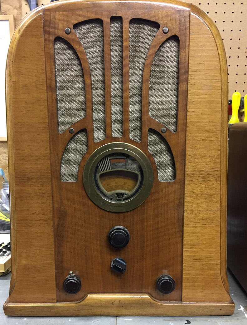
I just bought a couple antique radios from my brother-in-law. The radio that I am currently working on is a Philco 37-3640. Don’t look for it. It is a Canadian model. 

The receiver  is made in Toronto and is in fact a 37-640, well documented on yout site. I have  the original schematic of the 37-3640 and all available information for the 37-640.

The cabinet is made by Victoriaville Furniture, Victoriaville, Quebec, Canada.  No picture on the net exactly matches this cabinet so, I will share some whem I will found how to do it  ;-)
[Image: https://1drv.ms/i/s!AqDzjKUOhlam2wbYZMxTyBMexU8W]
I did some basic work (cleaning, visual check, short circuit check and replacing the power supply caps) and I can confirm that the radio is functional. Reception looks quite good. I now working an overall check starting with the power supply section. This is the reason of my questions here.
  1. There is a 2ohm resistor that shunt the 25 ohm part of the resistor in location 68 (may be a previous repair). This lower the bias voltage from -3.3V to -0.25 Volt. The change adds a lot of sensitivity to the receiver.  If I disconnect it, reception is quite bad.
    Have you seen this change before?
  2. On capacitor in location 66A, I read -22 Volts referred to ground/casing.
    Is it the correct voltage polarity?  In that case, the schematic shows the wrong polarity for the condenser and I need to swap my condenser.
Thanks in advance for your help.


Edit: Image added by admin
#2

Welcome to the Phorum!
Icon_wave

Nice looking set!
For those who might be able to answer your questions...here's the link to the 37-640 schematic.
#3

Thanks to the moderator to have added my picture.
See the schematic of the 37-3640 below. A re-organized version of the 37-640.
   

And a few more pictures of the receiver.
Cabinet plates


Receiver
   
   
#4

Hi and welcome,
>Is it the correct voltage polarity?
In this situation the + side is connected to the chassis and the - goes to the center tap of the HV winding on the power transformer.
I'll mention if you have an electrolytic capacitor that has been connected backwards do not reuse it, chuck it it's shorted.

When my pals were reading comic books
I was down in the basement in my dad's
workshop. Perusing his Sam's Photofoacts
Vol 1-50 admiring the old set and trying to
figure out what all those squiggly meant.
Circa 1966
Now I think I've got!

Terry
#5

I am closing this projet for now. Below is what I did, for reference. Hoping can that help someone - also valid for a 37-640 I guess. 
I did minimal restore and checks 1) was my first introduction in radio restauration 2) I don't want to risk breaking something as fragile as the dial disk 4) the design and assembly of this radio is quite complex 3) replacing all caps and resistors would let's me feel that is no more the same old radio...  
Finally, the radio works and perform quite good as is. Not a lot of humm, and I get a lot more radio stations than before. Will see in the future. I have a RCA M46 and M46A to practice - simplet in their design and assembly. 
Will rather improve the antenna for now.

   
#6

You may want to consider replacing #61,44,52,60,64,20, and 14. These are in the HV path and if leaky can cause excessive HV current. 41 and 43 are a good idea they can effect the tonal quality or cause noise.

When my pals were reading comic books
I was down in the basement in my dad's
workshop. Perusing his Sam's Photofoacts
Vol 1-50 admiring the old set and trying to
figure out what all those squiggly meant.
Circa 1966
Now I think I've got!

Terry
#7

Thanks a lot for your suggestions. Most seem quite easy to replace. I will certainly work this when I will do another restoration pass.


Users browsing this thread: 1 Guest(s)
[-]
Recent Posts
Jackson 715 not working
Now that you posted the schematic, I don't know why that Sprague electrolytic cap is across the meter, as it is not indi...MrFixr55 — 05:51 PM
HiFi (Chifi) tube amp build - but my own design.
What may be lacking in the PP Tube amps may be the 2nd harmonics, which some, especially RCA back in the day called &quo...MrFixr55 — 05:32 PM
Jackson 715 not working
Usually in an emission tester, the tube under test is measured as if it were a diode. So, some testers connect all the g...RodB — 04:17 PM
Restoring Philco 37-604C
Yep. F5 is green, D5 is Red. Red is Bad. Green is Clean.morzh — 01:30 PM
Jackson 715 not working
I did start to do that but I stalled out because I could not figure out how the grid and plate get voltage. In this diag...daveone23 — 11:52 AM
Restoring Philco 37-604C
(Insert Homer Simpson "DOPF" Here.) When all fails, look at the can. Took the Ron Ramirez advice, red Caig D...MrFixr55 — 09:23 AM
Philco 91 Speaker Replacement
From your text I am not sure if you intend to use the existing speaker with a resistor instead of the field coil. It wo...morzh — 08:44 AM
Philco 91 Speaker Replacement
My field coil is bad. I am still hoping to find an original, but if I can't I will go with a fitting Philco speaker, 125...dconant — 08:34 AM
Philco 91 Speaker Replacement
As Rod said, it is OK to use a fitting speaker, and then look for an original one. If you buy a Hammond 125 output tr...morzh — 08:15 AM
Philco 91 Speaker Replacement
Yes, I often have to substitute, then keep an eye out for an original. In the meantime, the radio is working and being e...RodB — 08:02 AM

[-]
Who's Online
There are currently 4598 online users. [Complete List]
» 1 Member(s) | 4597 Guest(s)
Avatar

>