01-10-2014, 04:18 PM
Brenda,
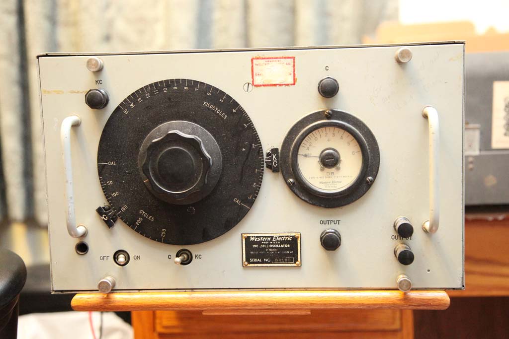
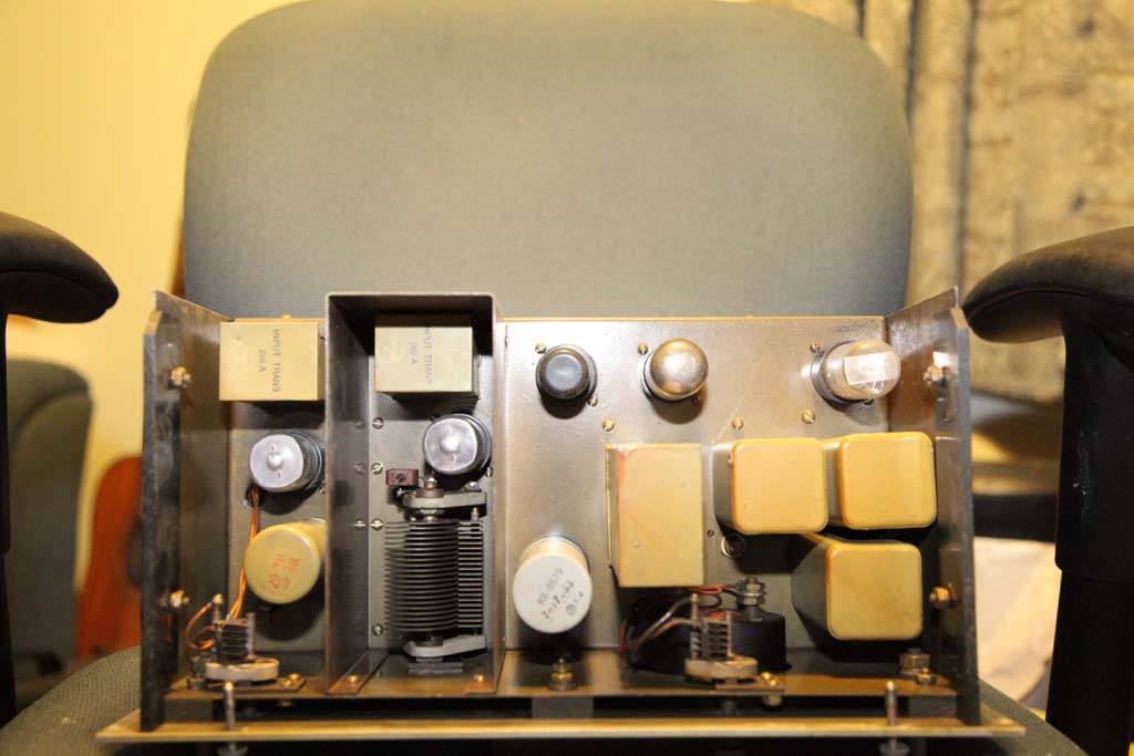
Here are some pics of the oscillator.
Face and chassis top.


Here are some pics of the oscillator.
Face and chassis top.
|
Not unlucky anymore, I guess....a tale of an audio oscilaltor. Thanks Brenda.
01-10-2014, 04:18 PM
Brenda,
Here are some pics of the oscillator. Face and chassis top.
01-10-2014, 04:19 PM
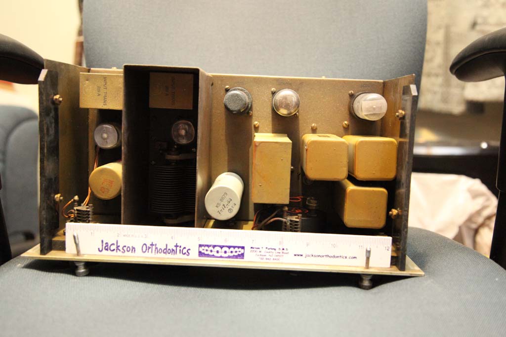
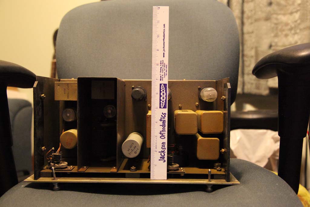
Underchassis.
01-10-2014, 06:43 PM
This looks to be a well thought out design. "hot chassis"? Perhaps, but well isolated from the cabinet and the outputs are isolated by capacitors. I note the ground bus is insulated from chassis by the bakelite standoffs, and the front panel is insulated from the rest of the chassis the same way. From the look of the design, there shouldn't be any hazardous voltage applied to any point accessible from the outside of the cabinet once the cover is in place.
01-10-2014, 08:08 PM
Brenda
Yes you are absolutely right, the first time I looked I hadn't noticed it: the chassis is mount of two large plastic sidings that keep it from contacting the front panel and the case. Capacitors alone woud not be sufficient, as low acoustic frequency dictates a cap that could present low impedance to a touch current should I decide to complete a circuit to something nasty, but the good news is the output is isolated by a transformer. That makes it that much safer. That is, in fact we do have a transformer isolation after all. Well, I was a litle impatient in buying that HP200, but.....truth be told, I always wanted HP200, so I used it as an excuse. Plus the price of it was low, so all is good. Now I just have to see if I could find a fitting plug. I don't feel like changing the power socket.
01-10-2014, 10:34 PM
That's a really interesting oscillator, and very well built as is typical of WE equipment. Looks like its a beat frequency audio generator where two RF carriers are mixed together to produce an audio signal.
Nice thing is that it can generate an audio sweep from 100 Hz to 15 KHz with one turn of the knob. Great for a quick check of audio freq response. Downside is that they are a bit unstable because you are subtracting two RF signals from each other, magnifying any freq drift. The waveshape may also not be a very good sine wave because of harmonics in the RF signals and nonlinearities in the mixing process. The HP 200CD is a true Wein Bridge oscillator and produces a very nice low didtortion sine wave. Its probably more suitable for critical testing, and of course its a classic HP design.
01-13-2014, 12:19 PM
So what do you guys and gals think?
I have these two electrolytics, they are from 1953. They can be seen on the pics above of the top and bottom. All are still measure pretty good. One dual 16uF measures 17uF and 20uF, another dual 16uF+50uF measures 20uF and 63.7uF respectively. I really hate to cut them open. They are probably military grade. 200V rated, and the voltage is low as it is a half-wave rectifier. I unsoldered them and have them out but can't bring myself to do it. Even though this thing has not been used since probably some time in 70s, I am not sure they need forming as the voltage will be half their working voltage.
01-13-2014, 01:57 PM
If it were mine I would reform them and then check for leakage. Those were very high quality caps and probably will still last longer than a modern replacement.
I have test equipment from the 40's and 50's with the original quality metal can electrolytics and they still test and perform as new. Sprague made a line of long life electrolytics and yours appear to be that type ( "2" in circle on top). I would connect each section in series with a 100K resistor and then connect to a high voltage supply to reform. Gradually bring up the voltage while monitoring voltage drop across the 100K. As the cap reforms the voltage drop will decrease and the cap voltage will approach the supply. When that happens you are done.
01-13-2014, 03:28 PM
Probably is what I will do. Just need a hi-V supply which I do not have.
I would really hate to cut open these guys. I could of course simply rectify the isolation transformer through a Variac and then a diode bridge with a 10uF cap to keep pulsations to minimum. I have all that here. And I have a bagful of 1N4007.
01-13-2014, 09:24 PM
I am reforming the first one. I found the article on reforming the exact caps I have. I am not following it directly as I do not have the dry battery and switch, but I am applying 180v ( film forming voltage for these is 160 to 200V) via 100K resistor, and I create the voltage with a bridge rectifier from Variac fro isolation transformer.
The voltage on the resistor is about 27v and so far has settled. I hope it will go down. 0.27mA is lots of leakage. PS. Started mo ing dow more.
01-13-2014, 10:09 PM
Now it is below 18V.
Well, I wish I started earlier today, it will roughly take a day per cap, so 4 days if all goes well. If not, will cut them open. In fact not bad, it is across a 100k resistor, usually the citerion of 10% after an hour is used with 20 to 50k resitor.
01-14-2014, 12:20 AM
Why not use two 100K resistors and do both sections simultaneously? As your voltage drop decreases, your forming current is also less so it takes longer and longer. At that point you can also reduce the series resistance to maintain a reasonable forming current of 1 mA or so.
Seems like you are doing pretty well if you only have 180 uA of leakage. I would be very happy with that result and reinstall the cap.
01-14-2014, 10:14 AM
This morning it was 50uA (5V left).
I was simply trying to see how it restores; tonight I will do two in parallel (I want to keep reforming the first one and start on the second). Tomorrow will do the other dual. And I think I will use 50K resistor as 20K to 50K (in some cases - 10K) this seems as recommended value and still keeps the current low. Hope they all reform. Will tell of the results later.
01-14-2014, 10:16 AM
Oh, and checked the tubes yesterday.
Only one tube is weak - one of the two oscillator tubes. The other are as strong as new or better (one is much better). But one osc tube is in the mid-red (I think 1,000 vs 2,500). I think it will still work though, it is not dead.
01-14-2014, 10:30 AM
What sort of tubes does it use? AA5 types like 35Z5, 35L6, 12SA7 etc?
How do all the other caps look? From the photos they all appear to be military grade micas, even the large chassis mount types. I have a feeling that after you reinstall the electrolytics, it will fire up and work fine as is.
01-14-2014, 11:04 AM
Exactly. At least the rectifier tube is the one (forgot others but yes, serialized filaments, one is 50V.....I could list them when I get home).
« Next Oldest | Next Newest »
Users browsing this thread: 4 Guest(s) |
|

|