07-12-2015, 03:39 PM
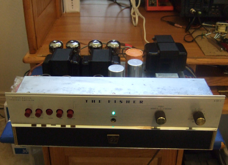
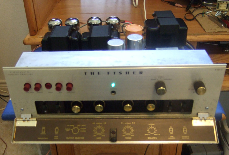
I finished the restoration of the X-101C with the help of Dave Gillespie on the AudioKarma.org site. I performed his EFB modifications as I went along in the restoration.
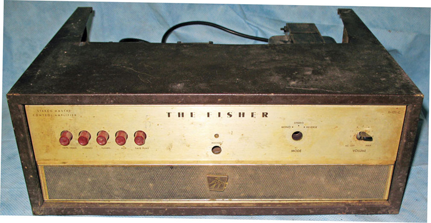
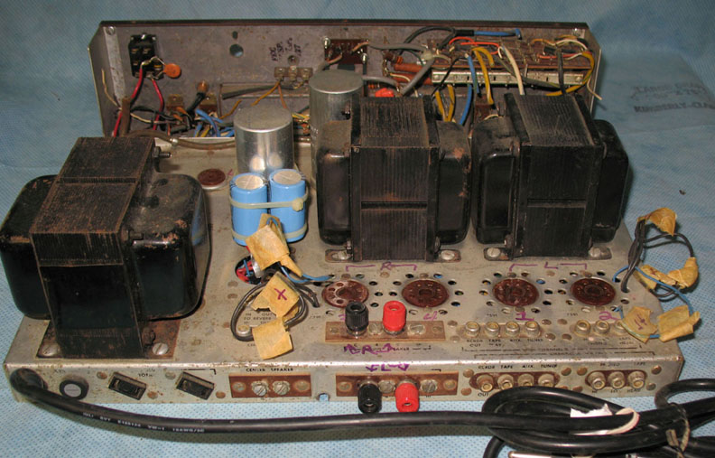
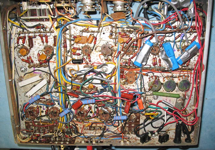
This poor amp had already seen modifications by a previous owner who only understood enough about electronics to connect things together. It had screen grid mods to the output stages, coupling capacitor values increased by using series parallel values (each one a set of 4 large caps enclosed in duct tape), much duct tape and masking tape, strange wire loops hanging above the chassis, B+ wires and audio cables cut throughout the amp, volume control removed, balance control and mode switch removed etc. Apparently the person was trying to change it into just a power amplifier.
I found replacements for the volume control on ebay, a new balance control, determined how to wire a new make-before-break switch to replace the missing mode switch, removed two added toggle switches. There was extensive corrosion due to being a roach motel for a while both top side and under the chassis. I spent many hours scrubbing and polishing with Weiman's metal polish and Eagle Nevrdull metal polish. Many wires had to be replaced and about 4 audio cables were sacrificed to replace some in the unit that were beyond repair. Most of the rest of the audio cables were repairable and so the original wire color codes were preserved for about 90% of the cabling. New slide switches were installed. RIAA/Tape equalization was deactivated and permanent RIAA equalization applied to both low level inputs, Equalization switch was repurposed as an on/off switch since the volume control I obtained did not have an AC switch on it. The speaker switch was rewired and the missing earphone jack was added. A new 3-pole 3-posn. make before break rotary switch was obtained from Allied Radio and wired to create the mode switch functions and installed. So now most of the original functionality has been restored. A new LV power supply was added that handles Dave Gillespie's EFB modifications that allow B+ variations to cause output tubes screen grids to track any changes and also the negative fixed bias to automatically track B+ changes too. Result is output tubes produce more power with less internal heat dissipation while also reducing distortion. A TL082 Op Amp is added between the preamp stages and the output circuitry allowing the unit to operate as a preamp or a power amplifier as desired. The interconnection point is the old "Reverb In or Out" jacks. The only visible difference externally is a small power transformer top side.
It finally received a new set of tubes and was changed from cathode bias to adjustable grid bias of the output tubes which are now Electro-Harmonix 7591s. Tests showed it produces about 30-32 watts per channel with one channel driven and about 26 to 28 watts with both driven when the output tubes are set to have 30-32mA current per tube. 10 ohm 1/4 watt cathode resistors allow accurate current measurements and also serve to act as a fuse in case a tube shorts. The same is done with the screen grid circuits - a 100 ohm series 1/4 watt resistor protects the output transformers from a shorted tube. I got to test that accidentally when a test probe slipped as I was measuring B+ and one screen grid resistor and cathode resistor immediately went open with a crack sound.
I have been listening to it now for about a week and love the sound.
Joe


