12-02-2013, 08:05 PM
Today after I managed to get the dial cord arrangements re-strung, I turned my attention to the dial lamp socket wiring.
The lamp sockets (there are 3 on this model) were all suffering from the rubber gone goo then turning to hardened tar syndrome mentioned in the post on this site about the sockets for Philco radios of this era. It is not too difficult to rework the sockets in most cases. I did have to go to Ace Hardware for the no. 6 nylon flat washer required. They were 13 cents each. I bought 3 of them.
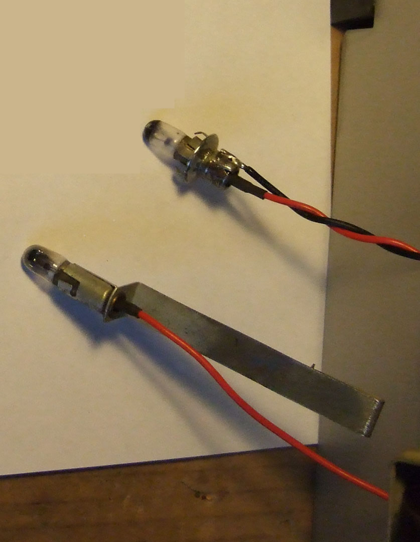
The two lamps for the dial attach at either end of the dial scale using a unique lamp holder bracket/socket assembly. I managed to get the old wire going to the center contact out and unsoldered the brass rivet. I used available new wire from other discarded electronic gear to handle new wire runs back under the chassis.

One thing that is different about this model is there is a power on indicator lamp that fits into a hole in the cabinet wood up front (top lamp in above photo). This socket is different in that it has some spring teeth that engage the wood to hold it in position securely. The mice had managed to cause corrosion on this socket similar to what they did on the chassis. After I managed to get the spring and original metal washer out of the socket, it took considerable effort to clean the corrosion out of the inside of the socket. For some reason, the washer did not want to move smoothly in the socket with the spring action. I had to do two things, polish the inside of the socket cylinder with some scotch-brite pad on the end of a screwdriver and filed down the OD of the nylon washer until smooth action was obtained.
All of the lamps are Tung-Sol No. 44 type. I may use 1847 lamps instead.
The front power indicator lamp is fed filament voltage after passing through a series resistor. The 40-200 schematic shows it to be a 10 ohm resistor. This one appears to be a 16 ohm resistor. I doubt there is any reason to use a different resistor than the 40-200 model.
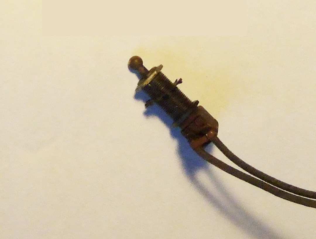
Next I need to find a new power toggle switch. It needs to have at least a 7/8 inch threaded shank to fit all the way through the 3/4 inches of wood at the front of the cabinet. I am pretty sure that is the way the radio was designed. There is no other on/off switch on the radio. The push-button controls only handle a phonograph RF tuned circuit and seven other AM broadcast station presets. The volume and tone controls have no switch on them. The OEM switch is hopelessly corroded from the mice and I do not trust it.

I may get the re-wired I.F. transformers connected back in circuit tomorrow.
Joe
The lamp sockets (there are 3 on this model) were all suffering from the rubber gone goo then turning to hardened tar syndrome mentioned in the post on this site about the sockets for Philco radios of this era. It is not too difficult to rework the sockets in most cases. I did have to go to Ace Hardware for the no. 6 nylon flat washer required. They were 13 cents each. I bought 3 of them.
The two lamps for the dial attach at either end of the dial scale using a unique lamp holder bracket/socket assembly. I managed to get the old wire going to the center contact out and unsoldered the brass rivet. I used available new wire from other discarded electronic gear to handle new wire runs back under the chassis.
One thing that is different about this model is there is a power on indicator lamp that fits into a hole in the cabinet wood up front (top lamp in above photo). This socket is different in that it has some spring teeth that engage the wood to hold it in position securely. The mice had managed to cause corrosion on this socket similar to what they did on the chassis. After I managed to get the spring and original metal washer out of the socket, it took considerable effort to clean the corrosion out of the inside of the socket. For some reason, the washer did not want to move smoothly in the socket with the spring action. I had to do two things, polish the inside of the socket cylinder with some scotch-brite pad on the end of a screwdriver and filed down the OD of the nylon washer until smooth action was obtained.
All of the lamps are Tung-Sol No. 44 type. I may use 1847 lamps instead.
The front power indicator lamp is fed filament voltage after passing through a series resistor. The 40-200 schematic shows it to be a 10 ohm resistor. This one appears to be a 16 ohm resistor. I doubt there is any reason to use a different resistor than the 40-200 model.
Next I need to find a new power toggle switch. It needs to have at least a 7/8 inch threaded shank to fit all the way through the 3/4 inches of wood at the front of the cabinet. I am pretty sure that is the way the radio was designed. There is no other on/off switch on the radio. The push-button controls only handle a phonograph RF tuned circuit and seven other AM broadcast station presets. The volume and tone controls have no switch on them. The OEM switch is hopelessly corroded from the mice and I do not trust it.
I may get the re-wired I.F. transformers connected back in circuit tomorrow.
Joe


