Starting 37-116 Deluxe Restoration
Posts: 15,301
Threads: 532
Joined: Oct 2011
City: Jackson, NJ
Is the grid pulled by 1M where it is supposed to and the oltage is correct on it?
Have you tried to change the tube?
The plate voltage comes from 3uF lytic cap, is the voltage on it good?
(This post was last modified: 10-18-2014, 06:41 PM by morzh.)
Posts: 126
Threads: 13
Joined: Sep 2013
City: Milwaukee, Wisconsin
(10-18-2014, 06:36 PM)morzh Wrote: Is the grid pulled by 1M where it is supposed to and the oltage is correct on it?
Have you tried to change the tube?
The plate voltage comes from 3uF lytic cap, is the voltage on it good?
You sir, are my hero. I traced back the grid to the bakelite cap 116 near the bottom of the schematic. Turns out I had accidentally switched the two wires running to it. Flipped them around, fired up the radio, and life is good. Volume works as expected. Voltages are in line pretty much across the board (+/- 15v or so). I guess I don't understand these circuits enough to know where to look for problems. Since the voltage was off on the plate, my first instinct was to check the connection to the plate.
The entire band 2 is just a whistling noise, even at the lowest volume. I wonder if that is a symptom of the open coil on band 2 as mentioned earlier in the thread by someone else. Not sure if I want to tackle that or not. It would require dropping the RF chassis again, and figuring out which coil it is. And seeing if I can fix it. The only coil I've ever fixed were the two outer windings on my 60B. And those were easy, simple like 15 turns. This little coils look a little more complex to fix.
Posts: 15,301
Threads: 532
Joined: Oct 2011
City: Jackson, NJ
Get the radio working first in general, then take care of smaller things.
When you get something resolved, like today, it is a good stopping point; take a breather, have a beer, read a poem or something.
Don't think of the whole scope, an elephant is eaten a bite at a time. 
Posts: 126
Threads: 13
Joined: Sep 2013
City: Milwaukee, Wisconsin
Oh, I took a break alright. To go help help my cousin and her kids move for the second day in a row.
Anyway, the radio is pretty much good to go. Only thing left is to mount the dial tower back on, and confirm the alignment is good (which I hope it is, this looks like a bear to align). But I'm not going to reassemble the tower if I have to drop the RF chassis to get to the band 2 coil(s). So I'm at the point where I decide to fix the coil, or button it up and call it a day.
Has anyone had experience rewinding the band 2 coils? I'm assuming it's the oscillator based on other posts I've found. I found posts where people say their coil is bad, but no one has really spelled out how the coil is wound. I think the only useful info I found when searching was that it appeared to be 40ga. I have some 38ga from when I rewound my 60 coils. If I went through with it, not sure if that would work or if I should get some 40ga
I was somewhat comfortable doing the 60 as those coils were well documented. So if anyone has tackled one of these and can give me some guidance, I'd appertate it.
Posts: 753
Threads: 48
Joined: Feb 2013
City: Shenandoah,
State, Province, Country: Pennsylvania
Hi Nick, your band #2 problem most likely is a bad oscillator coil #38 on the Philco schematic. There should be continuity between any and all 5 terminals on this beast. Mine is open and I did a rewind on it but I am soooo far from completing the restore on this chassis before I can fire it up and see if it works. I bought another complete RF deck for this radio but you guessed it, the same coil is bad on it too. I couldn't find anything on rewinding this so I tried meticulously disassembling it to count the turns and direction they turn but it disintegrated as I was going so not sure if I got a correct turns count or not. Like I said, I won't know if I did good for awhile. Good luck on yours.
Ron
Bendix 0626. RCA 8BX5. RCA T64
Philco 41-250. Philco49-500
GE 201. Philco 39-25
Motorola 61X13. Philco 46-42 Crosley 52TQ
Philco 37-116. Philco 70
AK 35 Philco 46-350
Philco 620B. Zenith Transoceanic B-600
Philco 60B. Majestic 50
Philco 52-944. AK 84
Posts: 126
Threads: 13
Joined: Sep 2013
City: Milwaukee, Wisconsin
I found a few threads here and at ARF about these coils. Someone pointed out that oscillator coils are very finicky. And Ron even said something about these "newer" (as compared to the ones used on the older models) Philco coils not being as forgiving as the older ones. So, the more I read about them, I think I'll just forgo band 2 for now. Maybe someday I'll look for someone with more experience than me to rebuild it.
So I mounted the dial tower back on and fired it up. It appears the alignment is off in every band. So, yay for that. I guess I'll give the alignment a run through. This one looks like fun.... I know some radios depend on other bands to be aligned in order to align them. Is not having a functioning band 2 going to mess with my ability to align the remaining bands?
Also, it appears the flood light switch broke again, as they are no longer functioning. Has anyone found a more permanent solution other than bending the tab back in the switch and hoping it stays?
Posts: 15,301
Threads: 532
Joined: Oct 2011
City: Jackson, NJ
I doubt your other bands depend on B2 as otherwise they would not work either.
I think (do not remember for sure) the oscillator alignment, which is a part of standard alignment anyway, is usually done using BC band, and the SW bands then are aligned using trimmer caps etc, but they are separate.
Posts: 126
Threads: 13
Joined: Sep 2013
City: Milwaukee, Wisconsin
Actually, I lied about the alignment. I missed the part in the dial calibration where you align to the index mark, then turn both the dial and tuner to to like 530, then move just the dial back to the index mark. After doing that, on BC its off by maybe 5kHz. The 5MHz time signal is coming in at like 5.02, the 10 is coming in at like 10.1, and the 15 is coming in at like 15.2. I think I'll just leave it. This thing does not look fun to align. Maybe even just tweak the dial to get rid of that 5kHz difference on BC, as that is mainly what I care about.
(This post was last modified: 10-19-2014, 06:38 PM by Nick3092.)
Posts: 126
Threads: 13
Joined: Sep 2013
City: Milwaukee, Wisconsin
Luckily, the switch is still functioning. One of the wires broke off one of the floodlights. Soldered it back on and it's functioning. So I guess all that's left is to finish assembling the handle on the dial, and then I can put it back in the cabinet.
Posts: 10
Threads: 8
Joined: Oct 2014
City: CA
Clean it, bend it a little (gently).
Deoxit helps.
The thankful receiver bears a plentiful harvest.
Posts: 126
Threads: 13
Joined: Sep 2013
City: Milwaukee, Wisconsin
Because I like complicating my life, I decided to give aligning this a whirl. In addition to all the SW bands being off, the magnetic tuning is definitely off, as I can hear a shift in tone and hiss when it's turned on/off. I know this adjustment can be very finicky. As I found a post from Ron saying you can align this set without hanging an external tuning cap off it, I decided to give it a go.
I usually align by AVC, so I have my VTVM hanging of pin 5 of the 6J5 AVC tube. I ran trough it all, and I seem to have it aligned pretty well. But the mag tuning is still off. I think I may have misiturpreted the directions though. For adjusting the primary of the magnetic transformer (81P), it says to crank up the generator to max and get minimum output from the speaker. If I'm watching the AVC, then I would really adjust this like any other adjustment - max negative AVC, right? I think last night I had a brain fart and was trying to hit more positive AVC with that adjustment, which didn't seem right last night.
So I think I need to run through it again tonight. Just want to make sure I am now correctly interpreting the adjustment on 81P. I guess I should confirm 81S as well. I would still adjust it to get the max negative AVC in that step, correct? I think I'm just getting confused by the min/max designations on the output, when I'm really watching AVC and should always be adjusting for max negative voltage there.
Posts: 126
Threads: 13
Joined: Sep 2013
City: Milwaukee, Wisconsin
I got it aligned, including the magnetic tuning transformer. I answered my own question in the process. If you are aligning by AVC then you just treat the mag tuning like any other adjustment and go for the most negative AVC. When dialed in to the sig gen at 1k full strength, I hear no shfit in tone when turning the mag tuning on and off, and the AVC stays perfectly steady. When tuning into a station, it works quite well. You can rock the tuner about +/- 10kHz and it stays locked on the station perfectly. Even works well on shortwave signals that tend to drift and are finicky to dial in.
I put it back in the cabinet, and it sounds great. There is a slight occasional crackle in the speaker. It's not too noticeable when the volume is up on a station. But you can hear it when the volume is low. I had an interstate transformer do that to me on an RCA where someone showed me how to bypass the primary to clear it up. That was much, much louder though. So maybe this is the early stages of the primary going bad?
It's not bad enough at this point to try and track it down. Just curious if anyone had any thoughts or ideas on troubleshooting that can easily be done with the radio in the chassis.
Other than that, just need to track down some station tabs. No one reproduces them as far as I can tell. I think I'll shoot RD an email and see if it's something they would consider, or how much it would be for a custom order. I'd be willing to cut them all out to save money on labor if they could print them up.
Posts: 15,301
Threads: 532
Joined: Oct 2011
City: Jackson, NJ
Nick, well congrats, it's a sweet feeling hearing this one play for the first time after you have just finished the alignment; I had mine, just the chassis, without even tuning mechanism/dial re-installed, on the table for several days just playing, me listening to its sound which is simply great. Even with the speaker out on the table.
(This post was last modified: 10-29-2014, 08:14 PM by morzh.)
Posts: 78
Threads: 3
Joined: Mar 2011
City: Howell, MI
Nice work, Nick!
I've had a 37-675 (no comparison to yours, though) on the bench, for a couple of years. You may have inspired me to finish this beast! I've done quite a bit, but there's still work remaining (RF deck stuff, flippin' rotten bulb sockets, new dial (I broke mine, like an idiot!) and send the cabinet out for a real finish. Mine has a bad coil, for band two, also! I won't dink with it.
Due to your achievement, I decided to "fire" mine up yesterday, after putting an extra length of hook-up wire on the antenna terminal, in order to reach my garage hung random wire antenna feed. I must complete this project!!!!!!
Again, great work, and thanks for your motivation!!!!!
-Greg
Posts: 126
Threads: 13
Joined: Sep 2013
City: Milwaukee, Wisconsin
(11-02-2014, 05:52 PM)gvel Wrote: Nice work, Nick!
I've had a 37-675 (no comparison to yours, though) on the bench, for a couple of years. You may have inspired me to finish this beast! I've done quite a bit, but there's still work remaining (RF deck stuff, flippin' rotten bulb sockets, new dial (I broke mine, like an idiot!) and send the cabinet out for a real finish. Mine has a bad coil, for band two, also! I won't dink with it.
Due to your achievement, I decided to "fire" mine up yesterday, after putting an extra length of hook-up wire on the antenna terminal, in order to reach my garage hung random wire antenna feed. I must complete this project!!!!!!
Again, great work, and thanks for your motivation!!!!!
Glad I could get you motivated again! I was afraid of the RF deck at first. But it's not that bad as long as you take pictures of all the wires coming out. And I also use those letter stickers to mark each wire I disconnected and I put a second one back on the tie point in the chassis I pulled the wire from. Those two things make it easy to reconnect everything, even a couple days later. The sockets are annoying, but easy to fix thanks to Ron's write up on them. It's a shame Philco had a bad run of coils on these. Seems like almost everyone that used this RF deck has a bad oscillator coil on band 2.
I did email RD about if they could make a reproduction call tab sheet (even if I cut them out myself). They never replied. Maybe I'll give them another email to nudge them to see if they reply. I know they've been busy trying to launch a new website. it's been almost a week though. I'll give it another couple days and email them again. In the mean time, I'll comb the craft stores and see if I can come up with some other viable material.
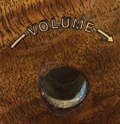
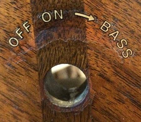
The volume and on/off/bass decals were pretty much rubbed off on the chassis. So i decided to see how well overlaying a new decal on them would line up. I found RD's decals were pretty far off from aligning on top of the remnants of mine. So much it looked pretty bad. So I tried he decals from AES. They weren't perfect, but they look much, much better then a bare spot or some kind of smudge.


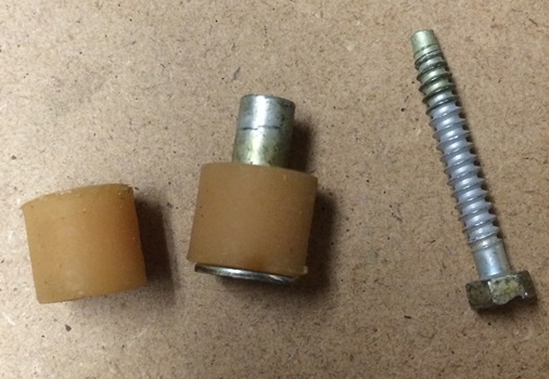
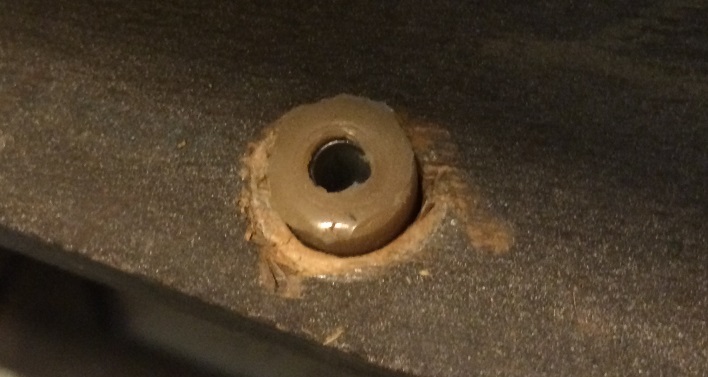
Another question I have is mounting the chassis. I got 4 new chassis washers from Ed at RR. As far as I can tell, this radio sits only on these 4, and has one screw with a sleeve on it that comes up through the back. The hole in the back is much larger than the sleeve though. So I don't even know what good that screw is doing back there.
Playing around with the grommets i bought for my 40-180 screws, I found 2 of them are almost a perfect fit over the sleeve. And they are about the same diameter as the sleeve. Was there originally a grommet on the sleeve? Also, how does this actually hold the radio in place? As you can see, the grommets fit through the hole. And the sleeve flange is the same diameter. So it also goes through the hole. The bottom side is also "counter sunk" with a larger hole. Like maybe a larger washer was supposed to go on on the sleeve. Does any one know for sure what the proper way is to install this screw and sleeve (washer/no washer, grommet/no grommet, etc...)?


Users browsing this thread: 1 Guest(s)
|


