Posts: 57
Threads: 12
Joined: Feb 2009
City: Prescott AZ
Just started working on a 38-116 (code 125) console. Chassis has been "worked on" before and about half the tube shields and bases have been cut off so that metal tubes could be used (ARGHHHH!).
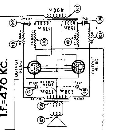
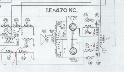
Anyway, in looking over the underside of the chassis I found that the input transformer (number 102 on the schematic) has problems. The two sections going from the grid of the 6L6 tubes are reading several kohms instead of the 150-175 ohms shown on the schematic. I did make sure not to include the 10,000 ohm resistors nos. 100 and 101 in the readings. Grid to grid of the 6L6s reads about 25K instead of slightly above 20K. The two 10K resistors have been replaced and both read 10K so they are not the problem.
Also, the 400 ohm section from the plate of the 6J5 driver reads about 750 ohms....
Any suggestions as to how to proceed?
Thanks,
Mark
Posts: 1,113
Threads: 14
Joined: Feb 2013
City: Irvington, NY
Is it possible that the transformer has been replaced? Maybe someone restuffed a replacement into the original sheet metal cover?
Its pretty strange for a transformer winding to increase in value rather than open completely. The original transformer is somewhat unusual in that it has a step down ratio and two independent secondaries. That's why I am thinking that it has been replaced with a more common step up interstage transformer. The dual secondaries are needed for the negative feedback networks connected from each plate of the 6L6's . If the present transformer is actually bad, you may have a hard time finding a suitable replacement, and might have to use a normal plate to P-P grid interstage transformer. In this case, you would have to eliminate the negative feedback networks (parts 98,99 and 103,104)
Posts: 57
Threads: 12
Joined: Feb 2009
City: Prescott AZ
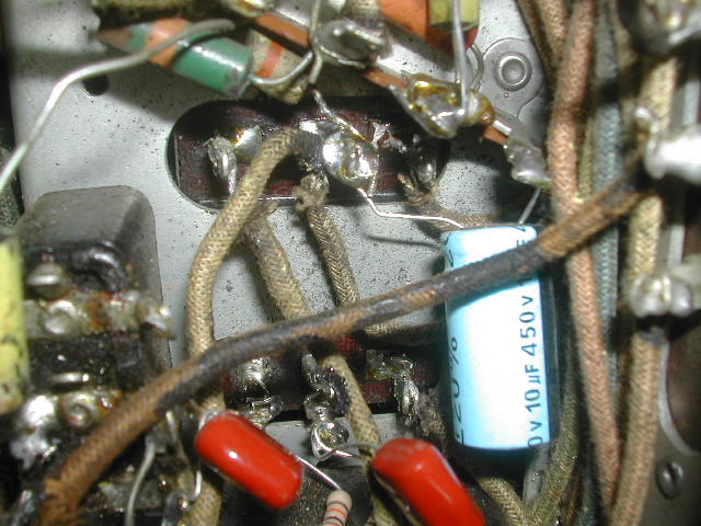
I checked the transformer. The case has the proper number stamped on it and the guts appear to be original. There are six tabs sticking below the chassis; three on each side. The grid from each 6L6 goes to an individual tab.
I've tried to show this in a closeup photo but it is very crowded there.
Posts: 1,113
Threads: 14
Joined: Feb 2013
City: Irvington, NY
Mark, the outside of the transformer may look original, but the innards may have been replaced. The solder connections definitely look like some work has been done. Here is a link to a page where just such a replacement has been described ( third topic):
http://www.oldradiosrus.com/build.html
You might try applying an audio signal to the primary winding of the transformerand see if it appears at the grids of the 6L6s, just to confirm if it is actually good or not.
Posts: 57
Threads: 12
Joined: Feb 2009
City: Prescott AZ
I will do that tomorrow. People have worked on this chassis in the past but it looks like it was limited to cutting off the tube shield bases to put in metal tubes; replacing some resistors and tacking on new capacitors in parallel with the old bakelite capacitors. Pretty sloppy work.
At some point I will remove everything going to the input transformer and remove it to check it out more throroughly.
I have seen other transformers that developed spots of corrosion leading to high ohm readings. I've jolted them with about 400-500V DC from my capacitor tester and have brought some of them (and some field coils) back down to a reasonable reading. If they are completely open it doesn't work.
Posts: 57
Threads: 12
Joined: Feb 2009
City: Prescott AZ
Mondial WAS CORRECT...
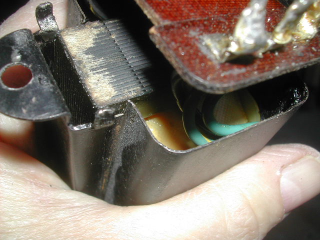
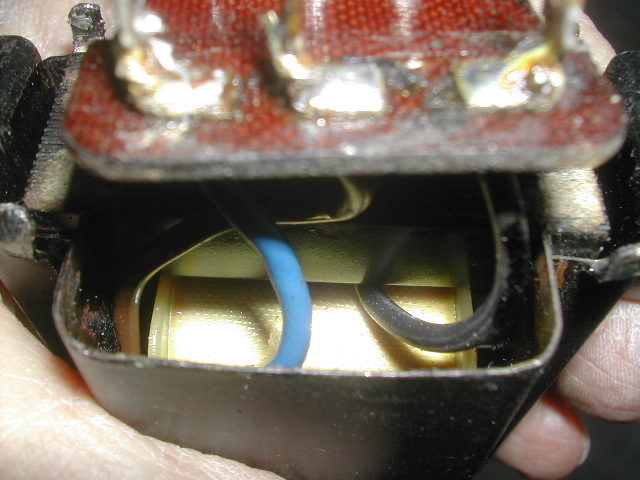
I pulled the input transformer and took it apart and it sure looks like a replacement transformer was put inside the original shell. It's a standard STEP UP transformer with primary reading 715 ohms and each secondary winding reads about 1.8Kohms.
SO, what do I need to do to make this work in the radio. I think it would be very hard to find a step down transformer with two separate secondary windings as the original was??
Thanks,
Mark
Posts: 15,306
Threads: 532
Joined: Oct 2011
City: Jackson, NJ
Well.....in the first place, why do you think you are having a problem with this transformer?
If you are in doubt as to its performance, see what turns ratio the original specs dictate, then do the simple AC voltage in-out test using a Variac to determine its turns ratio and if it is close enough, leave it in place.
Posts: 57
Threads: 12
Joined: Feb 2009
City: Prescott AZ
The original input transformer was a step DOWN transformer while this replacement is a step UP transformer. A local radio guy here says that using a step UP transformer will increase the gain on the output tubes and tend to introduce distortion. He would NOT remove the negative feedback circuit because that tends to reduce the gain which is needed even more since the replaced transformer is a step up transformer.
That seems to be opposite to what Mondial said yesterday on this thread. I am NOT a real good electronic theory person so I don't want to proceed until I have a good feel for what I should do.
Also, the local radio guy here (with about 40 years experience but not on this exact set) suggests maybe putting shunt resistors across the secondary windings to bring the measured resistance down from 1.8K ohms to something like 200 -400 ohms. Would the transformer (with a primary of about 715 ohms) then function as a step down transformer OR would I just be screwing things up even more?
Thanks,
Mark
Posts: 1,113
Threads: 14
Joined: Feb 2013
City: Irvington, NY
Mark, are there two separate isolated secondaries, or a single center tapped secondary? If it is center tapped, you can just remove the feedback networks and it should work fine with the step up ratio.
The reason for the original step down transformer was to provide enough current to drive the grids positive in Class AB operation. With the step up transformer you can just run in Class A with a few less watts output and you will never notice the difference.
Posts: 57
Threads: 12
Joined: Feb 2009
City: Prescott AZ
Mondial,
Thanks for the reply. Look at the partial schematic at the top of this thread. It looks like two separate secondaries to me.
One end of the two 10K resistors (one for each secondary winding) are tied together . From that tie point the wire goes through a 2K resistor to ground. Here is a bit more of that schematic section:
Posts: 1,113
Threads: 14
Joined: Feb 2013
City: Irvington, NY
Yes, but my question was if the replacement transformer you have now has the separate secondaries? Are there 6 wires coming from the replacement transformer itself or just 5?
Transformers with dual secondaries are pretty rare, so my guess is what you have now is a single center tapped secondary replacement.
(This post was last modified: 11-12-2014, 03:53 PM by Mondial.)
Posts: 57
Threads: 12
Joined: Feb 2009
City: Prescott AZ
There are six wires hooked up to the six lugs on the original terminal board at the bottom of the transformer case. I tested the secondaries with my ohmmeter and they appear to be separate with no common tap wire .
Mark
Posts: 1,113
Threads: 14
Joined: Feb 2013
City: Irvington, NY
Ok then. if the transformer has dual secondaries, you can keep the negative feedback and it should work fine, regardless of the step up ratio.
I just saw your further comments:
Quote:The original input transformer was a step DOWN transformer while this replacement is a step UP transformer. A local radio guy here says that using a step UP transformer will increase the gain on the output tubes and tend to introduce distortion. He would NOT remove the negative feedback circuit because that tends to reduce the gain which is needed even more since the replaced transformer is a step up transformer.
The step up transformer will increase the gain of the output stage, but you can just turn down the volume to compensate. It will not introduce distortion unless you try to play it too loud. If the replacement transformer has dual secondaries, you can keep the negative feedback. The feedback will not work properly if the replacement is a single center tapped winding.
Quote:Also, the local radio guy here (with about 40 years experience but not on this exact set) suggests maybe putting shunt resistors across the secondary windings to bring the measured resistance down from 1.8K ohms to something like 200 -400 ohms. Would the transformer (with a primary of about 715 ohms) then function as a step down transformer OR would I just be screwing things up even more?
Shunt resistors are not a good idea. You will just be loading down the output without changing the turns ratio to step down, which will cause distortion and clipping in the driver stage.
Posts: 57
Threads: 12
Joined: Feb 2009
City: Prescott AZ
Thanks for all your help. I will replace the out of spec resistors and wire the transformer back in place with the neg. feedback circuit intact. I have a long way to go on this set but this is a good start.
Regards,
Mark
Users browsing this thread: 1 Guest(s)
|


