Posts: 7
Threads: 2
Joined: Dec 2014
City: california
hello.
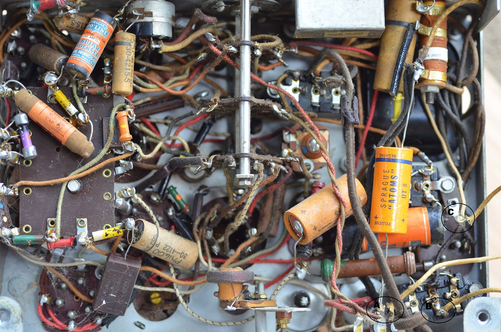
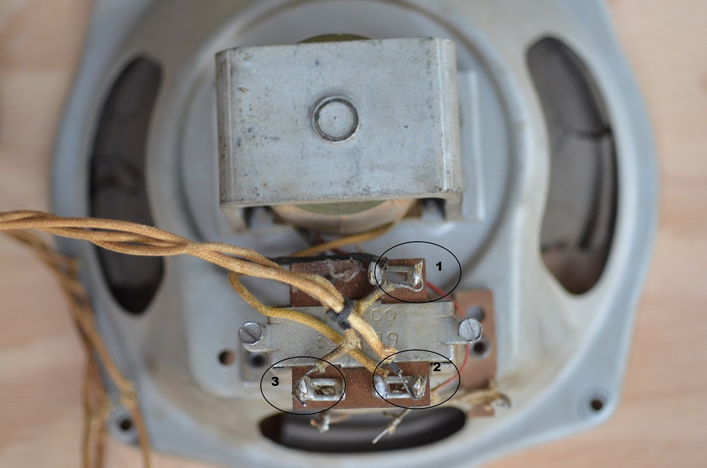
I have a 640-B that upon removal from the cabinet i lost the orientation of the speaker wires.
would you guys be able to look at the pictures below and let me know how to re-orient them?


thank you.
Posts: 15,307
Threads: 532
Joined: Oct 2011
City: Jackson, NJ
I would say, get the schematic and go by it.
I do not have 640B sch, and 640 might not be the same.
And you have to measure the transformer's leads to see where the centertap is or where the field coil comes in.
Unless someone knows off hand.
Posts: 13,776
Threads: 580
Joined: Sep 2005
City: Ferdinand
State, Province, Country: Indiana
Well, first off, the photos shown are not of a 640. Probably a 620 or 625. Model 630 and larger all have speaker sockets; 620B and 610B tombstones have hard-wired speakers.
A 640 speaker would have four terminals above the audio output transformer on the speaker; this one only has three, so it is a single-ended output, which also points away from a 640.
Smitty, how many tubes does this radio have?
--
Ron Ramirez
Ferdinand IN
Posts: 13,776
Threads: 580
Joined: Sep 2005
City: Ferdinand
State, Province, Country: Indiana
--
Ron Ramirez
Ferdinand IN
Posts: 7
Threads: 2
Joined: Dec 2014
City: california
(12-11-2014, 10:30 AM)Ron Ramirez Wrote: Yup, that's a 620.
http://www.nostalgiaair.org/Resources/804/M0013804.htm
Six tubes...correct?
your right about the six tubes. the only info my dad got with the radio is that it was a 1935. and the model number tag is Missing.
we looked at the schematics we found, but its not as clear as a wiring diagram would be.
i could post a scan of it if it would help.
i also could post a picture of the cabinet if needed.
the one thing we think we figured out from my notes is the console is #10175
its an S-14 speaker
voice coil and cone #36-3157
field coil and pot #36-3495
Posts: 13,776
Threads: 580
Joined: Sep 2005
City: Ferdinand
State, Province, Country: Indiana
(12-12-2014, 12:20 AM)smitty Wrote: the only info my dad got with the radio is that it was a 1935.
It is a
1936 model, which came out in the summer of 1935.
And it is most definitely a 620.
Cabinet 10175...I'll have to look that up.
--
Ron Ramirez
Ferdinand IN
Posts: 7
Threads: 2
Joined: Dec 2014
City: california
(12-12-2014, 06:20 AM)Ron Ramirez Wrote: (12-12-2014, 12:20 AM)smitty Wrote: the only info my dad got with the radio is that it was a 1935.
It is a 1936 model, which came out in the summer of 1935.
And it is most definitely a 620.
Cabinet 10175...I'll have to look that up.
I thought it might be obvious to you guys hence the pictures.
However i can put a meter across them . What would i be looking for if i did?
Posts: 7
Threads: 2
Joined: Dec 2014
City: california
(12-11-2014, 10:02 AM)morzh Wrote: I would say, get the schematic and go by it.
I do not have 640B sch, and 640 might not be the same.
And you have to measure the transformer's leads to see where the centertap is or where the field coil comes in.
Unless someone knows off hand.
it turns out that its a 620
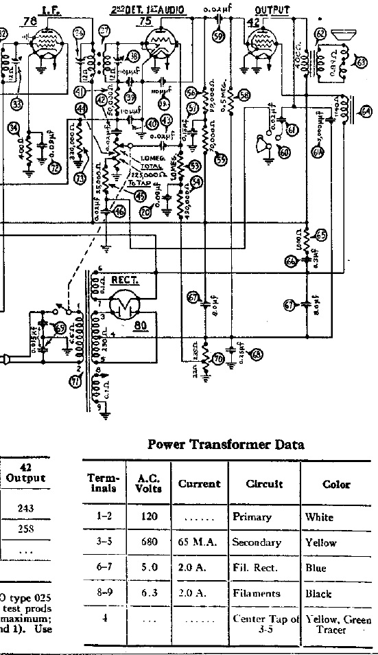
so here's the section of the schematic that shows the transformer and mentions the center tap.
the components are listed as follows:
62 = output transformer
63 = voice coil and cone assembly
64 = field coil and pot assembly
71 = power transformer
do you mind walking me through identifying things?

Posts: 15,307
Threads: 532
Joined: Oct 2011
City: Jackson, NJ
Ok
The three wires are likely to be:
1. The end of 64 field coil that goes to cap 66 and rectifier filament and power trans pin 6.
2. The second end of 64 FC that goes to one end of the audio xfmr primary (connects to 42 Screen Grid)
3. The other end of audio xfmr primary (goes to plate of 42 tube).
Now.
Mesure ohms between any two prongs.
Write down the resistance. It can be:
1. 1.1 kOhm
2. 400 Ohm
3. 1.5 kOhm (sum of the above).
Now. Choose the combination that gives you 1.5kOhm.
Mark the pins A and B.
Measure from any of the two to the third pin which you mark as C.
Lets say If it is 400 Ohm it is your auio primary and then
pin A is your 42 plate
pin B is your FC rectifier end
Pin C is your FC connected to audio xfmr primary.
Connect
A to 42 Plate,
B to The end of 64 field coil that goes to cap 66 and rectifier filament and power trans pin 6, and
C to the Screen Grid of 42.
(This post was last modified: 12-14-2014, 07:01 PM by
morzh.)
Posts: 7
Threads: 2
Joined: Dec 2014
City: california
(12-14-2014, 07:01 PM)morzh Wrote: Ok
The three wires are likely to be:
1. The end of 64 field coil that goes to cap 66 and rectifier filament and power trans pin 6.
2. The second end of 64 FC that goes to one end of the audio xfmr primary (connects to 42 Screen Grid)
3. The other end of audio xfmr primary (goes to plate of 42 tube).
Now.
Mesure ohms between any two prongs.
Write down the resistance. It can be:
1. 1.1 kOhm
2. 400 Ohm
3. 1.5 kOhm (sum of the above).
Now. Choose the combination that gives you 1.5kOhm.
Mark the pins A and B.
Measure from any of the two to the third pin which you mark as C.
Lets say If it is 400 Ohm it is your auio primary and then
pin A is your 42 plate
pin B is your FC rectifier end
Pin C is your FC connected to audio xfmr primary.
Connect
A to 42 Plate,
B to The end of 64 field coil that goes to cap 66 and rectifier filament and power trans pin 6, and
C to the Screen Grid of 42.
thank you will try that out when i get over to my dads for the holidays


