Model 90 Output Transformer
Posts: 26
Threads: 4
Joined: Feb 2016
City: Nelson
State, Province, Country: BC
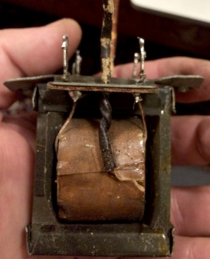
Here's what my 1931 Jefferson Electric 2766J Audio Output transformer looks like, first the primary side:

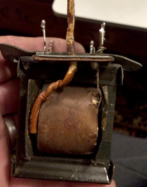
And here's the secondary:

As I reported earlier, the primary side reads around 160 ohms from start to finish, but the center tap is not connected. The secondary is wide open.
Posts: 7,215
Threads: 266
Joined: Dec 2009
City: Roslyn Pa
Just for grins I'd check the connections where the secondary is soldered to the lugs. It's a little odd for the secondary to be open as the wire size is a bit heavier.
GL
Terry
Posts: 26
Threads: 4
Joined: Feb 2016
City: Nelson
State, Province, Country: BC
Hi Terry, I thought of that, too. I did resolder the connections, but still no go. I thought I'd try to do a bit more investigation before I give up, though. There is a Ham swap meet tomorrow, so maybe I'll get lucky...
Posts: 15,305
Threads: 530
Joined: Oct 2011
City: Jackson, NJ
Could be pure mechanical damage or rot.
I am yet to see an open secondary myself.
It simply lacks reasons to burn. But rot it could. From flux residues. For example.
People who do not drink, do not smoke, do not eat red meat will one day feel really stupid lying there and dying from nothing.
Posts: 7,215
Threads: 266
Joined: Dec 2009
City: Roslyn Pa
<There is a Ham swap meet tomorrow, so maybe I'll get lucky...
Happy hunting!!!
Terry N3GTE
Posts: 15,305
Threads: 530
Joined: Oct 2011
City: Jackson, NJ
For 20,90 pushpull, 77 to 111 with 45 pushpull 125CT series is optimal. Though many xfmrs will work, they won't work correctly. The voice coil of these speakers is around 0.7 ohms and it needs to be converted with 1:10,000 ratio to present the needed impedance. 125C has many various ratios. Most other xfmrs are created for 8 ohm coils.
People who do not drink, do not smoke, do not eat red meat will one day feel really stupid lying there and dying from nothing.
Posts: 26
Threads: 4
Joined: Feb 2016
City: Nelson
State, Province, Country: BC
Well, I got to the Ham Swap meet a bit late today (darn GPS!) but I managed to pick up a nice Precision 192 tube tester in very good condition, and a good price. Nice wooden box, too. So not a total loss! I got back to looking at the 2766J output transformer and deconstructed it a bit to see if I could figure out the true connections. The secondary connections were obvious when I saw what I was looking at, and they are NOT open, they work just fine. However, the primary side still is connected only between one of the 3 possible combinations. The other 2 combinations are infinite ohms...To see if I could understand it better, I attached my variable AC and monitored the input and output voltages. For the one good combination, I got 1V out at the secondary for 15 volts in. So something is very skewed if this should be a 100:1 turn ratio. Long story short, a Hammond 125C is on order and will arrive in a couple of weeks. Thanks again for all your input.
Posts: 107
Threads: 20
Joined: Feb 2015
City: Los Angeles, CA
(03-04-2016, 09:07 PM)rrova Wrote: Yes, I can see that it's been worked on before. The soldering was not well done. I've re-soldered a number of connections that were sloppy or loose. Also, lots of very thin wiring that I've started replacing with vintage cord.
Someone had published the schematic for a model 90 using PP 45's about three or four months ago, on this site. I am sorry I don't recall who, However I do have the diagram and it does work, because I needed it for my own use. It shows the 4 pin plug as well as the output transformer and field coil wiring. I am willing to make a copy and mail it to you if you wish, or I can take a picture of the sheet and e-mail it to you. Tubesforme (Michael)
Posts: 15,305
Threads: 530
Joined: Oct 2011
City: Jackson, NJ
People who do not drink, do not smoke, do not eat red meat will one day feel really stupid lying there and dying from nothing.
Posts: 26
Threads: 4
Joined: Feb 2016
City: Nelson
State, Province, Country: BC
(03-08-2016, 02:51 PM)morzh Wrote: Michael
http://philcoradio.com/tech/images/90a.jpg
Thanks, if that's the diagram, I do have that version. Otherwise a photo/email would be great!
Posts: 15,305
Threads: 530
Joined: Oct 2011
City: Jackson, NJ
This is the P-P 45 output Philco diagram.
This website has other 90s, like P-P 47 and SE 47 versions.
I have a P-P 45 myself and used this one.
People who do not drink, do not smoke, do not eat red meat will one day feel really stupid lying there and dying from nothing.
Posts: 26
Threads: 4
Joined: Feb 2016
City: Nelson
State, Province, Country: BC
Just got back from the PO and picked up my Hammond 125C transformer. Wow, fast service from Angela Instruments LLC. I ordered it Sunday night and it was cross-country in my hands by Wednesday a.m. Decent price, too. $34.19 + shipping. Now let's see if I can wire it up correctly ;)
Posts: 15,305
Threads: 530
Joined: Oct 2011
City: Jackson, NJ
Luckily you need a pushpull. An SE transformer is always more, thus 12CSE is $47.69 vs $36.92 for P-P.
People who do not drink, do not smoke, do not eat red meat will one day feel really stupid lying there and dying from nothing.
Posts: 107
Threads: 20
Joined: Feb 2015
City: Los Angeles, CA
(03-08-2016, 05:17 PM)rrova Wrote: (03-08-2016, 02:51 PM)morzh Wrote: Michael
http://philcoradio.com/tech/images/90a.jpg
Thanks, if that's the diagram, I do have that version. Otherwise a photo/email would be great!
It isn't the Philco Schematic, however it looks like it was done by Philco. The diagram shows the 4 pin plug, (pins facing you) the output transformer, field coil and speaker. The drawing is titled Philco 90 Early-Speaker Assembly (Push-Pull 45 output tubes) I recently used this diagram when rewiring my K-2 speaker, which is the one used in the Philco Model 90. I will e-mail it to you tomorrow. Hope it will help you. It sure helped me. Michael
Posts: 26
Threads: 4
Joined: Feb 2016
City: Nelson
State, Province, Country: BC
Thank you very much, Michael. I will look forward to receiving it. I can use all the help I can get on this!
Users browsing this thread: 1 Guest(s)
|


