Posts: 1,181
Threads: 48
Joined: Oct 2017
City: Allendale, MI
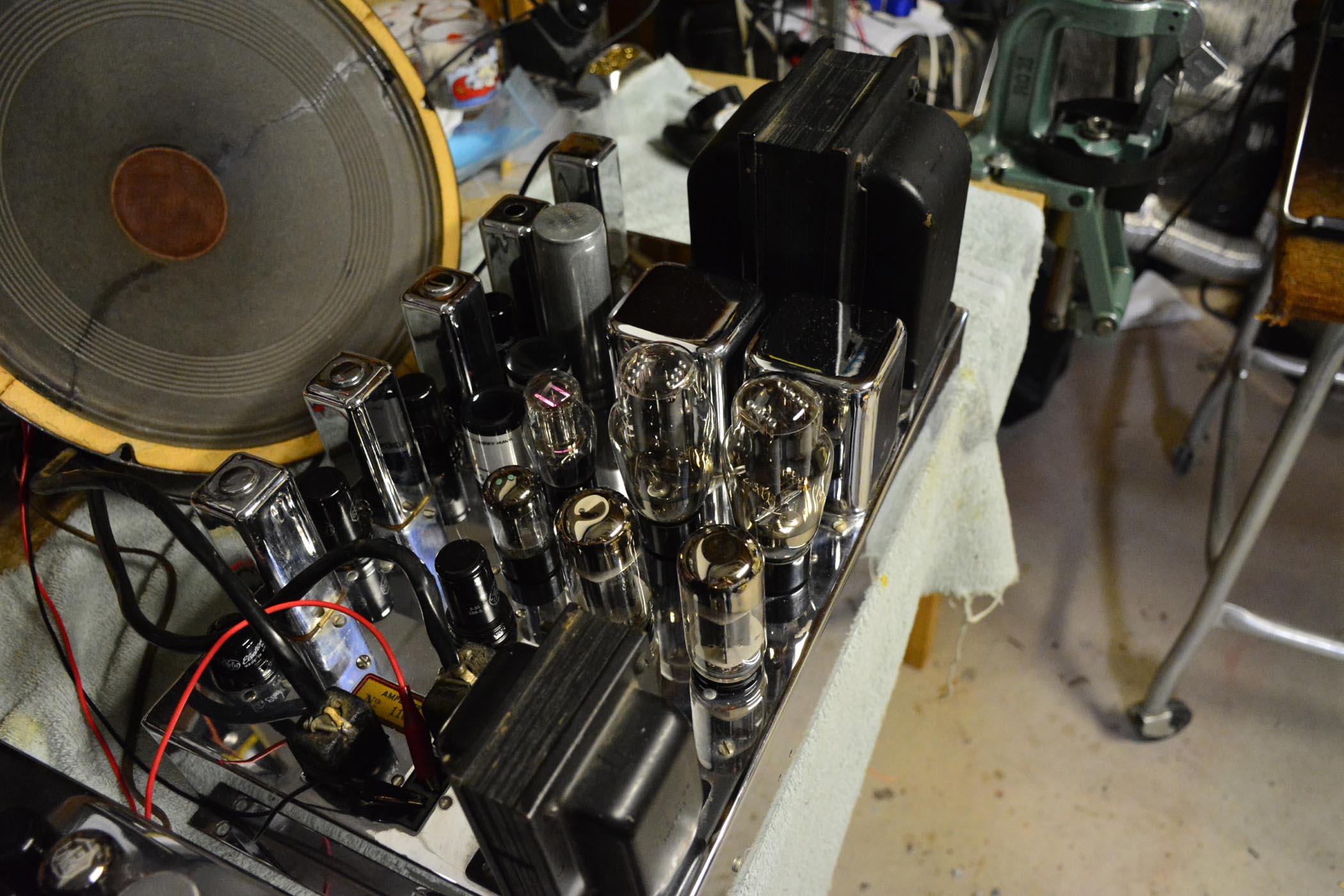
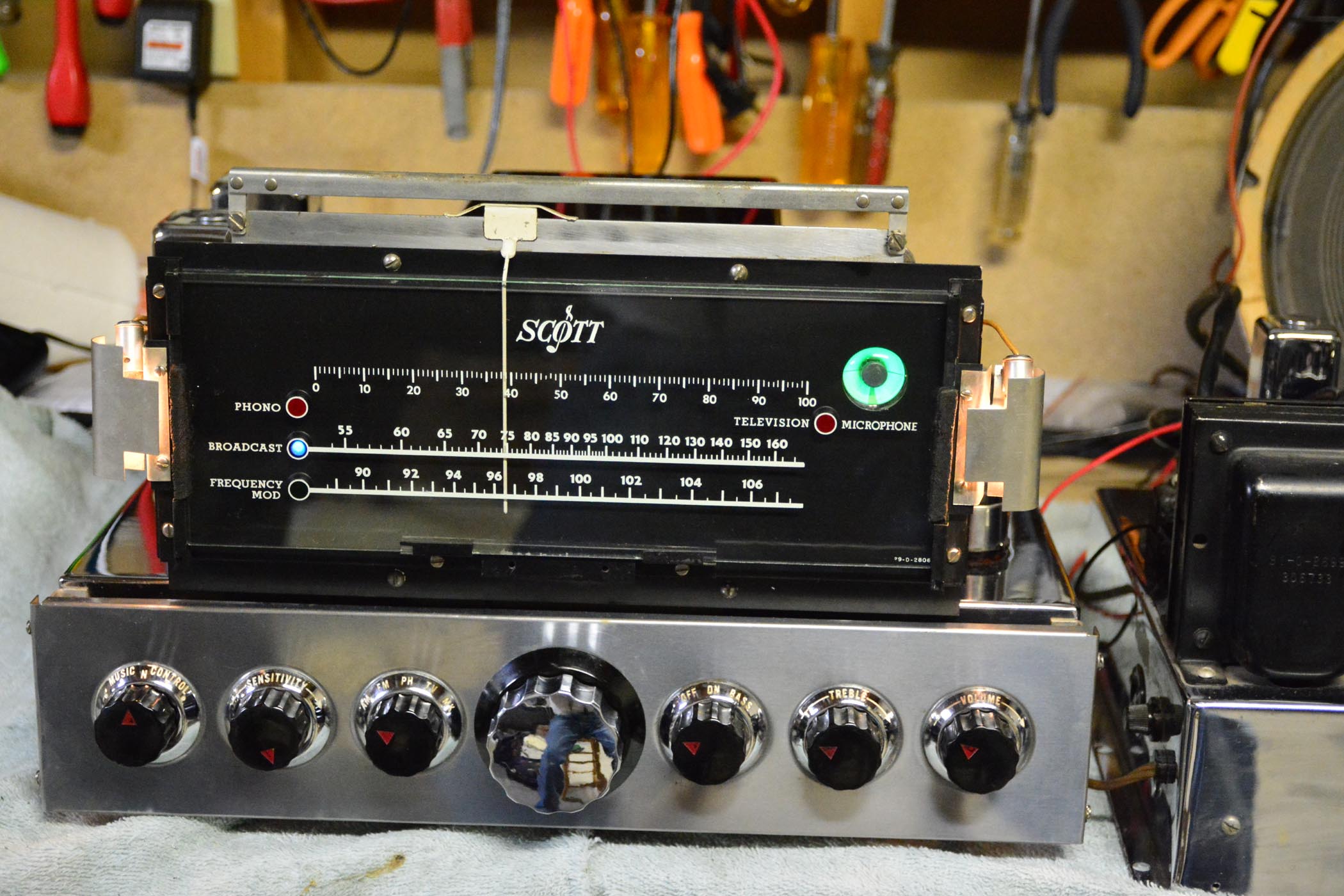
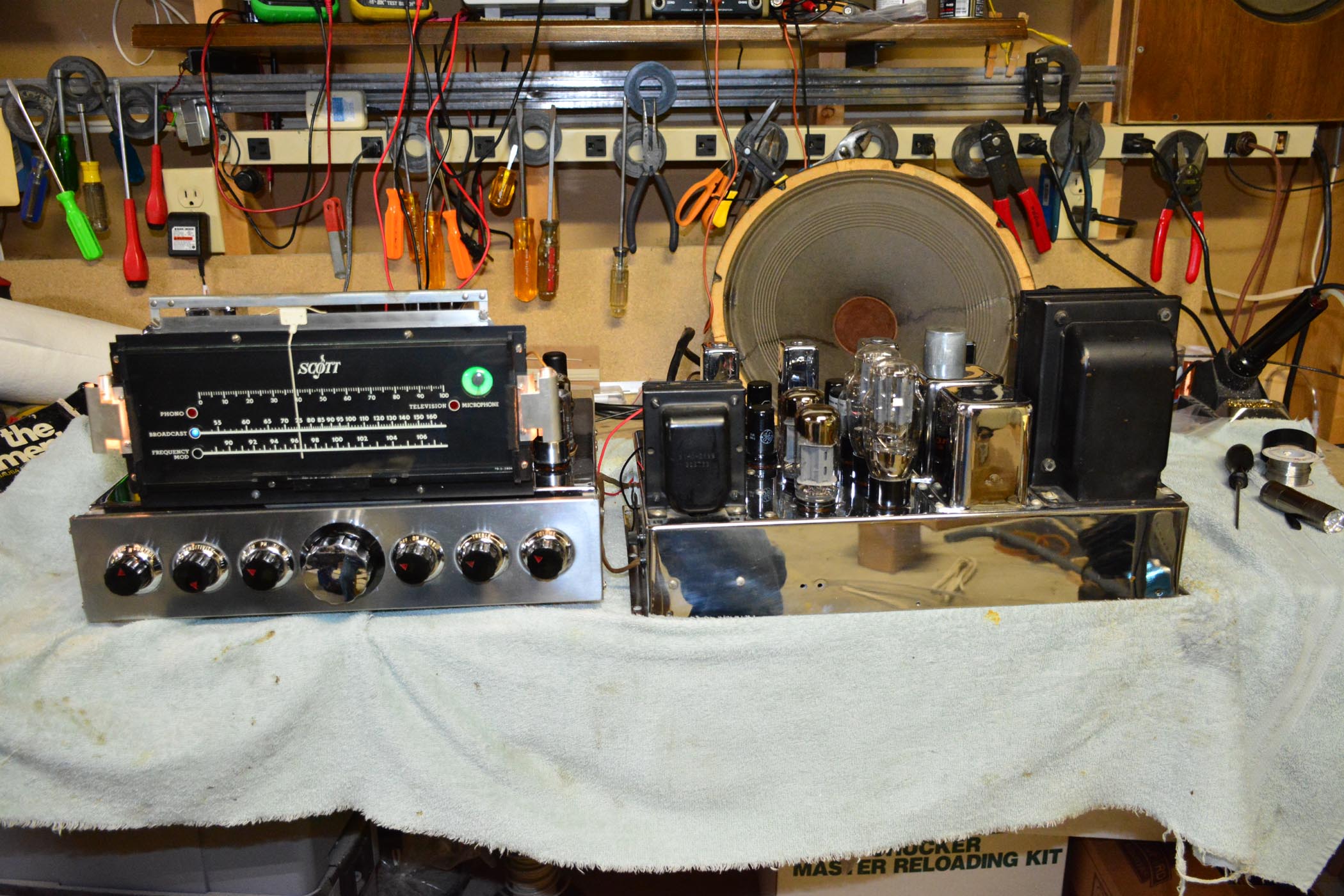
While waiting for some re-chroming to get done on my Scott 16 (1937), I decided to tackle this Scott 16A (1947). A much newer radio than I've handled so far and has FM. I have the AM aligned and sort of the FM. Never done an FM alignment before so I still need to do a bit of work. Seems even the presence of and the movement of my body near the chassis affects meter readings when aligning the final FM stage that is part of the discriminator. I'd like to try the FM alignment using my O-scope but need to do a little research on that yet. FM sounds great, though. The speaker is not original to the radio but is close. It is a 15" Jensen coaxial that seems to give some fairly clean highs. I need to build a cabinet for it so that I can get some lows out of it.
Stuffed all of the tubular caps and the electrolytics. Had to replace several resistors. They are all the more modern molded carbon type. Several 1/2 watt resistors of 220K and 330k values were open. I decided to change all of those values since it seemed to be a common theme. Most of the other resistors were well within spec so I left them.
There are a lot of Tobe and Sangamo molded caps that look like Mica's. Not sure that all of them are. anyone know about these brands of Mica lookalikes? Any info would be good. I would rather not replace all of them if they are a good cap, as there are quite a few of them in this radio. Except for the "Music Control", which is some sort of noise reducing circuit, the radio is working great.
this radio will be a shelf queen in my shop area and will provide entertainment when AM just gets too noisy to endure. FM will be nice.


(This post was last modified: 01-28-2018, 02:06 PM by rfeenstra.)
Posts: 312
Threads: 30
Joined: Jul 2017
City: Hay Lakes, Alberta,Canada
Wow! Looks very nice! Good shop radio ;)
Posts: 15,307
Threads: 532
Joined: Oct 2011
City: Jackson, NJ
It's in wonderful shape, no need of cosmetic anything, just recap. I wish I were that lucky 
People who do not drink, do not smoke, do not eat red meat will one day feel really stupid lying there and dying from nothing.
Posts: 1,181
Threads: 48
Joined: Oct 2017
City: Allendale, MI
Hmmm. Not so much luck. It's as simple as money can make it! I paid dearly cuz I really liked it and didn't want it to get away. It's minus a cabinet and originally would have a turntable. I have none of that, but didn't really care since it's for my shop where I wanted FM and a nice looking chassis. As I said, I recapped the tubular and electrolyic caps. Still not sure about the Tobe and Sangamo caps. Radio works great and didn't replace any of them so I have my fingers crossed.
Speaker is now in an enclosure - an old speaker cabinet from an Allen Organ. Sounds much better but a little disappointed an the amount of bass. Probably have to design and build a cabinet designed to match the speaker.
(This post was last modified: 01-30-2018, 05:42 PM by rfeenstra.)
Posts: 481
Threads: 18
Joined: Jan 2013
City: Mesa, AZ
I would be proud to have that; er... near my feet when I wake up in the morning... 
Posts: 1,181
Threads: 48
Joined: Oct 2017
City: Allendale, MI
I like nice looking chassis, chrome or otherwise!
Posts: 1,181
Threads: 48
Joined: Oct 2017
City: Allendale, MI
Okay all of you FM gurus, I confess lot a lot of ignorance on FM discriminator technology (and a lot of AM stuff too!). On weaker stations, I get a bit of 120 cycle hum when tuned slightly off. As tuning is brought in precisely, the hum diminishes until virtually gone at one precise dial setting. Is this typical of discriminator operation? Where does the hum come from? Do I have an alignment problem? When doing the alignment, it was interesting to watch the DC offset at the output of the discriminator vary as tuning was adjusted. I set the the discriminator for 0 volts DC when the signal level was the greatest as determined by the AGC signal. Is it possible that the hum is coming in early in the system and the weak signal is not being fully limited to eliminate AM, and that when the discriminator is perfectly balanced in its tuning that the AM is cancelled out? Just curious if I have a problem or if it is normal operation.
Posts: 2,118
Threads: 112
Joined: Jun 2010
City: Medford OR (OR what?)
OK, let's see those restuffed caps. 
I have one of these too. I don't think it is as nice as yours. No cabinet or place to display it, so it is just sitting on a project shelf.
"I just might turn into smoke, but I feel fine"
http://www.russoldradios.com/
Posts: 1,181
Threads: 48
Joined: Oct 2017
City: Allendale, MI
Thanks Russ. I have no cabinet either. It's on a shelf in my shop and I've been enjoying it immensely for several hours a day. FM is SOOO much quieter in a modern house than AM and the extended frequency range is great. I used to do a bit of recording and mastering CD's so high end audio is part of my blood. No stereo here, but hey, can't talk about imaging, sound stage, depth, instrument placement etc. while walking around in the shop anyway.
Capacitors... I re-stuffed all electrolytics, tubular paper caps, and oil filled caps. I am afraid there are a LOT of what look like mica's that are probably molded paper. I was hoping to avoid those, but someone on the Scott forum said they were paper and to replace them, particularly in the noise reduction section. I don't use that so it is in reality out of the circuit. If you think that some of those caps could be causing the hum on de-tuned, weak FM stations then I'll have to look into doing that. How do you make those look original? Most of them are Sangamo and Tobe. Do you know anything about them? The only time the hum is problem is if the frequency drifts a tiny bit, which it does until on for quite a while. No auto frequency control. I do have to wait for silence to fine tune the hum out. My favorite classical station is fairly weak so the hum becomes noticeable on quiet passages, and I have to re-tune. I do notice sometimes, though, that high frequencies like sibilance in a speaking voice seem a bit distorted. But not always, and not on all stations. Is it possible that some stations broadcast with distortion? maybe I expect too much from a 1947 radio!
I'd like to try to do another alignment someday. I need an excuse to purchase a spectrum analyzer. Would such an instrument aid in aligning the FM section? (Say "yes" so I can justify the purchase!) I watched a YouTube of Carlson's Lab doing an alignment on a Hallicrafter, I believe, and it looked useful. In fact, he said it was mandatory for proper alignment of that radio.
Posts: 2,118
Threads: 112
Joined: Jun 2010
City: Medford OR (OR what?)
For special radios I have made molds for recasting those caps, like with the resistors. There are some pictures on my blog of the ones I made for both of the Strats I did recently. They were .01 as I remember. This is a large value for a mica cap and a giveaway that they are in fact paper.
I would have to look at the schematic, but I would rather cut one leg than leave them in circuit and that is assuming that they are part of an unused circuit. (as you say)
One of our local AM stations has quite a bit of hum in it's mod, but no distortion. I would recommend taking a look at them and replacing any suspected as being paper - even if you can't recast them, for now.
"I just might turn into smoke, but I feel fine"
http://www.russoldradios.com/
(This post was last modified: 03-03-2018, 08:04 PM by Phlogiston.)
Posts: 1,181
Threads: 48
Joined: Oct 2017
City: Allendale, MI
I didn't really want to hear that, but yes, i knew that I would eventually be looking at replacing them. Yuck! Do you use a spectrum analyzer?
Posts: 1,181
Threads: 48
Joined: Oct 2017
City: Allendale, MI
A lot of 6200 mmf caps in the FM IF section. these are very likely not mica's? I could find one of the listed replacement cap brand's part number and it does show up as mica for that brand. I could not cross the other brands listed to verify. To replace them with mica's is very expensive from mouser.
(This post was last modified: 03-03-2018, 10:54 PM by rfeenstra.)
Posts: 2,118
Threads: 112
Joined: Jun 2010
City: Medford OR (OR what?)
Sweep generator and a good scope.
"I just might turn into smoke, but I feel fine"
http://www.russoldradios.com/
Posts: 1,181
Threads: 48
Joined: Oct 2017
City: Allendale, MI
Well, the 16A started to produce some unwanted noises and symptoms I didn't like after playing beautifully for several months. I decided it was time to dig into the Tobe and Sangamo molded caps. I could not find even 1 Tobe cap that measured anything reasonable on my fluke DMM. Every Sangamo measured fine (perhaps the Sangamo caps are all mica's???). I realize that the Fluke is not a perfect cap tester, but my replacement caps all measured fine with this meter. Anyway, they are replaced, the radio re-aligned ( and it did re-align better than before), and it plays again. Now we'll see if it holds up.
I have a question for the 6L6 aficionados out there. The push pull is self biased using a 210 ohm cathode resistor, 402 volt plate voltage, 277 volt screen voltage. This yields a -20 volt grid voltage with 95 ma idle current for both tubes. Most data sheets on the 6L6 talk about a grid bias more like -30 volts. These are new Solvtek tubes that I've had in my inventory for maybe 25 years. Is my idle current within reason or should I increase the size of the cathode resistor to shut the tubes down a bit? Perhaps these cheap Solvtek tubes have a bit different characteristics than original 6L6's??
Thanks for your input!
Rob
(This post was last modified: 05-07-2018, 11:30 PM by rfeenstra.)
Posts: 15,307
Threads: 532
Joined: Oct 2011
City: Jackson, NJ
There are many Sovtek 6L6 tubes, I have their Tung Sols I just bought. Depending on the lettering they will have different plate voltages etc. And they are not cheap.
6L6GC STR matched quad is $90 from Jim and $108 from somewhere else. These have higher plate voltage than regular 6L6G.
In my HF22 the self-bias voltage is -35V (100mA for both tubes across 350 ohm resistor).
If it were for CLASS A amp, I would say be mindful or displacing the working point too much so it will start distorting; for this which is I think AB see if your crossover remains smooth.
Personally I trust the engineers who calculated the working point of the amp.
People who do not drink, do not smoke, do not eat red meat will one day feel really stupid lying there and dying from nothing.
Users browsing this thread: 1 Guest(s)
|


